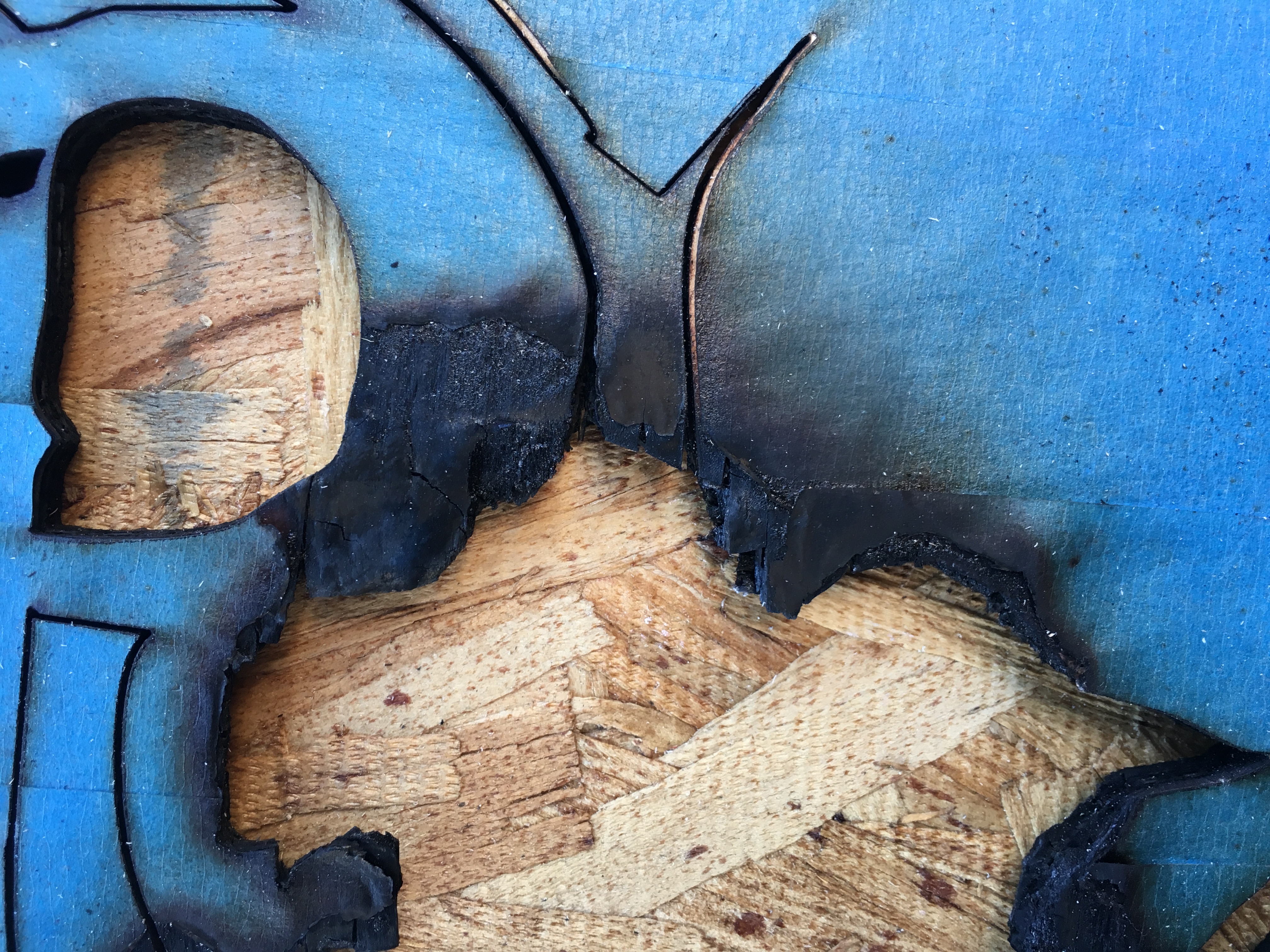
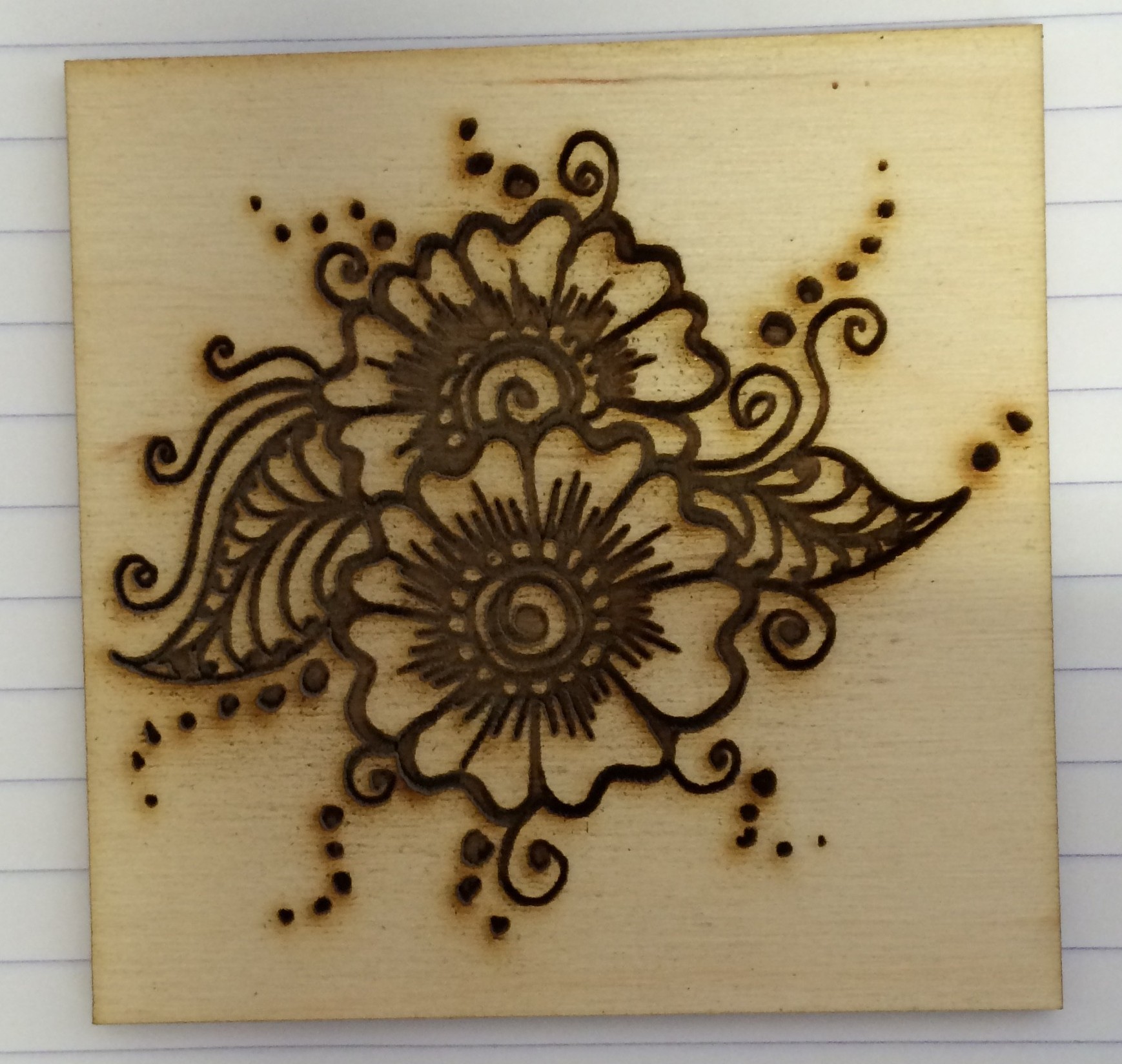
If your job looks like this, either you’re trying to cut some thick material that’s beyond the capability of our laser, or else you have chosen your settings poorly. This kind of burning generates a lot of smoke and flying embers, which can contaminate the optics and lead to expensive repairs. If you see this kind of result, please STOP right away and rethink your job.
Category Archives: Tip
Bugs Can Be Anywhere
During class last night, we ran into a problem where parts of the user interface in Retina Engrave 3D were being disabled. The controls for setting raster power, for instance, were grayed out, and some (but not all!) of the menus at the top of the screen were also unresponsive.
It’s not too unusual for the laser software to get confused and need to be closed and restarted. That didn’t help. We tried closing and restarting CorelDraw, too, without success. We tried closing and restarting both at the same time. We even tried rebooting the computer. Nothing seemed to help.
Then Laura suggested power cycling the laser itself. That worked! We were all surprised, since it isn’t at all obvious that the laser software even talks to the laser before starting the job (beyond the connection monitor in the lower left corner, that is), but apparently it does.
So, when things go off the rails in a bizarre way, don’t forget to try power cycling the laser.
Print Scale Factor
During class last night, it seemed like everything we printed was coming out a bit bigger than we intended. After class I tracked this down to a setting in the CorelDraw print dialog. On the Layout tab, you can control “Image position and size” for the print. By default, it is set to “As in document”, so what you drew is what you get. You can also choose “Fit to page” or “Reposition images to”, and with the latter setting, you can set a scale factor, or even separate scale factors for horizontal and vertical. Somehow the scale factor got set to 1.16, which makes everything print 16% bigger than drawn.
This is a useful feature to know about. But please, if you use a feature like this, try to remember to set it back to the default before you go, to avoid causing problems for the next user.
Two Inkscape Quirks
Recently Jon ran into two problems printing to Retina Engrave 3D from Inkscape. We don’t understand all the ins and outs, but there would appear to be some bugs somewhere. I’ll describe the symptoms and the workarounds we found. Maybe that will be helpful if you happen to run into similar problems.
Problem 1 manifested as missing vector objects. That is, some of the stuff that was drawn in Inkscape mysteriously didn’t make it onto RE3D’s vector screen. What we found was that one of the vectors had been drawn with partial transparency. That is, its A (alpha) setting on the Stroke Paint tab of the Fill and Stroke palette was set to a value other than 255. Apparently this made that vector block out other objects in its vicinity from being printed.
Problem 2 was that the raster screen in RE3D only showed part of the drawing. In this instance, a yellow vector rectangle had been drawn around the entire drawing with the express purpose of forcing the raster and vector screens to have the same extent (a useful trick that allows you to print subsets of your drawing and keep everything in perfect alignment). However, the vector rectangle was being ignored for raster purposes, even though it showed up on the vector screen. A workaround for this was to fill the rectangle with yellow, and move it all the way to the back of the drawing so it didn’t interfere with any of the other raster data.
So, if you use Inkscape:
- Don’t use transparency in drawings for the laser, and
- Fill objects you need to see on the raster screen.
Engraving Henna Patterns
Engraving Tiles
I found some very inexpensive 3″×6″ ceramic tiles at Home Depot. These. They have a nice glossy black finish and they only cost 26 cents each. I decided to try to engrave them. I was hoping to be able to blast cleanly through the black glaze and reveal the bright white ceramic underneath. It didn’t exactly work out that way.
Here are pictures of my results. The upper left tile is blank. The one below it has been vector engraved at two different power levels. The three on the right have been raster engraved at varying speeds and powers.
The raster engraving never did reveal any clean tile. The bluish tint I believe came from the blue paper towel I used to wipe away the ceramic dust after engraving.
Below is a close-up view of the lower power vector effort. It’s pretty clean, but the line is wide and not very deep. The lighting for this photograph makes it look brighter than it really is. 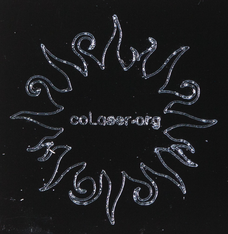
Here’s an angled close-up of the higher power vector attempt.
The material bubbled up and created a mess above the plane of the glaze. Here I’ve made some attempt to scrape it away, but the result is still not clean at all.
You can buy tiles that are designed to be laser engraved. These cheap tiles from the hardware store are no substitute.
Engraving Slate (with a jig)
I found some slate coasters on the bargain shelf at Jo-Ann the other day, and tried laser engraving them. The results were pretty good! See the photo gallery below.
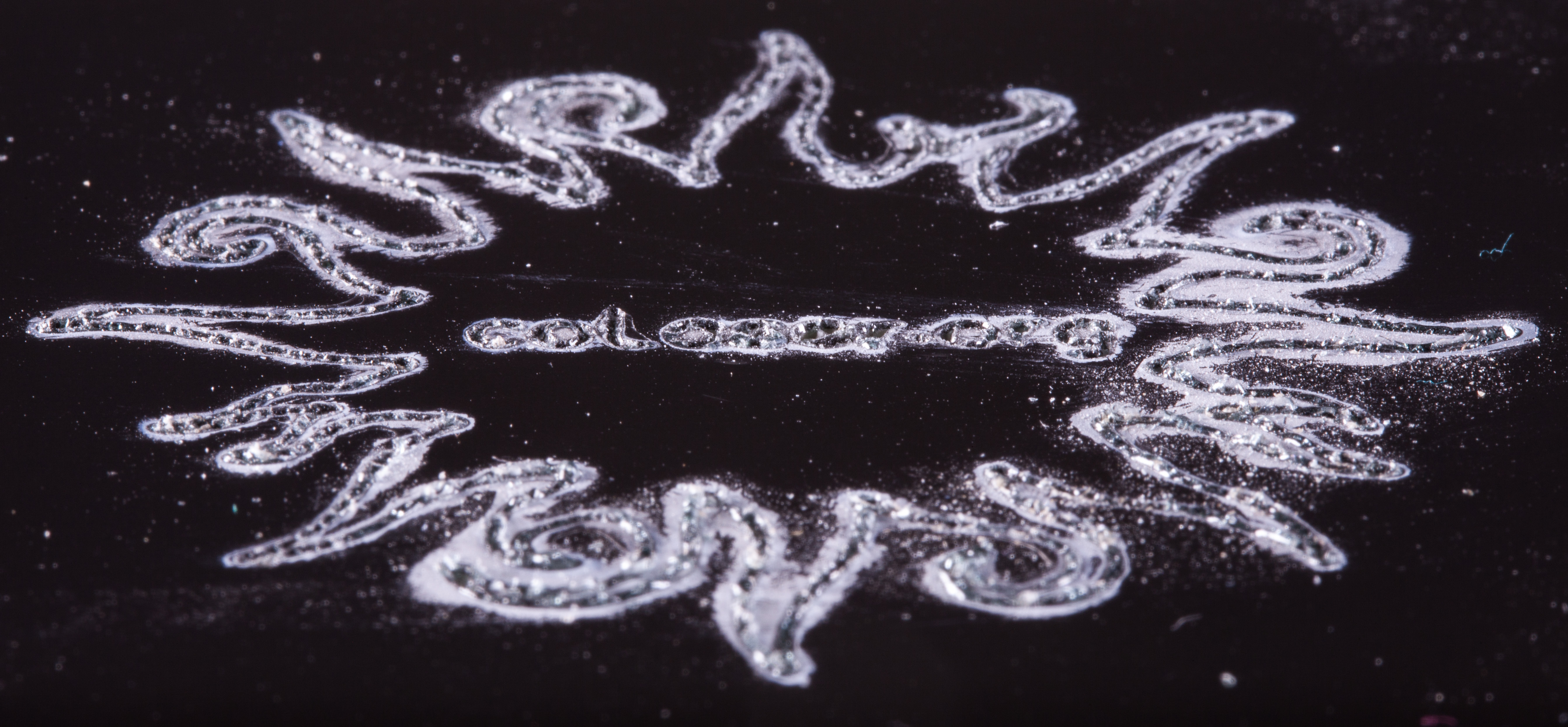
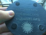
I first tried vector engraving some text. This worked nicely. The engraved line was wider than we usually see on wood or acrylic, but that just made the letters more legible. Full power and full speed seemed to work as well as anything. Slowing it down just made the letters look a little sloppier, without making them much deeper. It also noticeably warmed up the whole coaster.
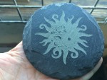
My first raster engraving test was again at full power and full speed, at the lowest resolution (252 dpi). It successfully changed the color of the surface, except for a few tiny spots that were still black. It didn’t create any relief I could feel, though, just a subtle texture change. Turning the speed way down did create lots of relief, and I ended up choosing a setting midway between those two for a moderate amount of relief. Fine interior details were squeezed out by the greater effective line width; that could have been compensated for in the artwork.
This material reacts to the laser in ways I haven’t seen before. When hit with vectors, some of the material seems to melt and form thin glass-like bubbles above the surface. They easily wipe away with a paper towel, exposing the carved letters. When hit with the raster, though, the excess material appears in the form of very fine white dust. Much of the dust is deposited on the surface. Because of the ventilation air flow, all the dust ends up toward the rear of the engraving. The dust is easily wiped off. I didn’t see any evidence of the dust getting into the laser’s optics.
Whether vector or raster engraved, the lasered areas are lighter in color than the rest of the surface. I don’t know exactly why. The black surface removed by the laser might be the result of natural aging, or it might be a factory-applied treatment. It might also have something to do with the rougher texture of the lasered surfaces. It will be interesting to see what color the engraved areas are after some time passes.
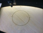
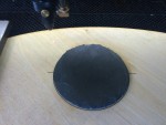
Since the laser always starts every job at the upper left corner of the rectangle that encloses the art, it’s not so easy to precisely place the laser head in the right place relative to the round coaster. To solve this problem, I created a simple jig. In CorelDraw, I added a vector circle around the outside of the raster artwork I wanted to engrave. I placed a piece of scrap material into the laser and engraved just the circle guideline on it. Then, without moving the laser head, I placed the coaster on top of the scrap and (after refocusing) centered it in the circle. I could then run the raster job and be sure the artwork would be lined up on the coaster just as I intended.
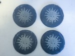
In fairly short order I was able to make a set of four coasters. With the simple jig the engraving is consistently centered so they look good even side-by-side.
- Vector engraving of the text “colaser.org” at various settings. The material bubbles up to make these interesting formations. They are extremely thin and fragile. I wiped them away with a paper towel.
- First raster engraving test. At this power level (full power and full speed), the color changes (with a few spots left black) but the cut is so shallow it’s hard to detect.
- Second raster test, still at full power but with reduced speed. The cut is perhaps too deep now.
- Raster artwork combined with a vector circle to guide material placement.
- Here’s the alignment jig engraved on a piece of scrap.
- Here’s the first coaster placed carefully into the alignment jig.
- After engraving. The white dust is deposited during engraving. You can see that the exhaust air flow is enough to blow the dust toward the rear.
- Final result, with the speed set in between the two tests. Nice! You can see that the interior cutouts are too spindly, because the effective cutting size is pretty big.
- A set of four coasters. With the alignment jig it’s easy to keep the sun centered consistently on the coaster.
Keypad Features
Here are some keypad functions you might not know.
Pause a Running Job
When a job is running, the key with the locked and unlocked padlocks on it will pause the job without losing your place. You can hit the same key again to resume where you left off. This seems to be much more responsive than the pause button on the computer screen.
Pausing the job can be handy. For example, if you see that a weight you used to flatten out the work piece is going to be in the way, you can pause the job long enough to move the weight. As long as you’re careful not to move the work piece, you probably won’t be able to tell that the job was ever paused.
Cancel a Running Job
When a job is running, the yes/no key on the far right will cancel it completely.
Quickly Move the Head
In FX (Fast XY) mode, the yes/no key will quickly jump the head to the top left of the table.
Respond to a Fire
Using both of the two previous functions is a good response to a minor flare-up of fire. Hit yes/no to cancel the job, and then immediately hit yes/no again to jump the head away from the fire. This works because FX mode is the default when a job ends.
Jog the Bounds of Your Job
Once you’ve used the J key on the computer to send the bounds of your job to the laser, or run your job once, the key with a square of four arrows will run the bounds again. You’ll be in a better position to see the results when you’re standing at the keypad.
What’s more, you have extra flexibility. In the FX (Fast XY) mode, the keypad key runs the bounds just like the J key on the computer. In the SX (Slow XY) mode, it runs the bounds more slowly, making it easier to check critical boundaries. In the FZ (Fast Z & Test) mode, it runs the bounds quickly, but just one side at a time. Hit the key again to run the next side. Finally, in SZ (Slow Z & Test) mode, it runs the bounds one side at a time, but more slowly.
Run Your Job Again
Once you’ve run a job, if you want to run the exact same job again, go into SX (Slow XY) mode and hit the yes/no key. The LCD will ask if you want to do that. Hit the yes/no key again to confirm. You’ll get exactly the same job as last time, even if you’ve changed some settings on the computer screen since then. If you want to use the new settings, you have to go back to the computer and type the G key or click on the play triangle.
You can reposition the head before re-running the job, to create multiple separate copies of your piece. You could also re-run the job without repositioning the head, in order to cut and engrave everything a little deeper. If you’re trying to cut very thick material, it might be useful to raise the Z axis table a bit before re-running the job.
Raster Image Size Limit
During class exercises today, we discovered that you can’t just use the maximum paper size for all cases. If you try to print raster data on the 48×36-inch paper size, the results are (sometimes?) so big the software discards the raster data. There’s no error message or long delay, it just throws away your data. You can then go crazy trying to figure out what’s wrong with your CorelDraw (or whatever program) file.
Since extremely large raster jobs are impractical anyway (because they take too long to run), this is not a severe limitation. It just means you need to choose a reasonable paper size when you’re doing a raster (or raster-then-vector) job. Most raster jobs will probably fit on the default Letter size paper, as long as your drawing is kept within the page margins.
I didn’t search for the precise limit on paper size for raster data. It might depend on the file contents and on the way the drawing program formats the data. Just be aware that there’s a limit.

