Another Power Supply Failure

The problem described in the previous article persisted for days. Sometimes it would disappear for a short while, and then come back suddenly. Users were informed of the problem and the possibility of workarounds, as described in that article, and were able to get some work done.

On July 2, Marcus reported that the laser had been working great and then suddenly was not firing at all. I thought that sounded like the power supply had in fact been faulty for a while, and had now finally given up the ghost. I offered some possible experiments that would help to rule out other possibilities.

On July 3, I set aside some time to work on the problem, and brought the new power supply that I had ordered as a potential solution. A quick test verified Marcus’s report: everything was working except the laser wasn’t firing.

I opened the lower right-hand service doors and looked at the power supply. It didn’t take long to notice that none of the LED indicators on the power supply was lit. At least the red power LED should have been on, if AC power going into the power supply was good. I checked that with a digital multimeter, and sure enough, there was good AC power at the input of the power supply. Definitely something was wrong in the power supply.

This is not a huge surprise. In the 12 years we’ve been operating this laser (including some time off for the pandemic), we have only seen a few hardware failures, and several of them have been in the high voltage power supply. In fact, all of those failures have been the exact same: we saw diminished laser output power, followed by zero output power. In each case, this was caused when the internal surge suppressors (or “inrush current limiters”) failed. Slowly, and then all at once. The first time that happened, I consulted with the importer/manufacturer, Full Spectrum Laser in Las Vegas. Somewhat to my surprise at the time, they suggested that I open up the high voltage power supply and inspect visually for failed components. I guess they knew what I’d find: fried surge suppressors.

And here’s what I found this time:

Yup, more fried surge suppressors. The pattern of symptoms wasn’t exactly the same as before, but the failure mechanism was the same.

For reference, this is what they look like in the new power supply:
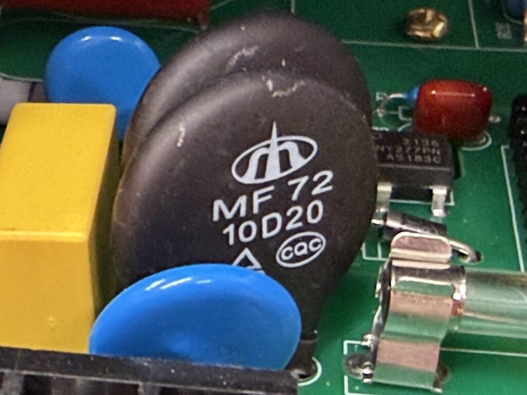
This is a slightly different circuit layout and a slightly different surge suppressor device. Maybe the new design will be more robust; only time will tell.

Back when this failure happened the first time, I ordered six new surge suppressors, so that I could replace both of the failed units and have spares for two more failures. But now I was out of spares, having (I think) used all the spares on subsequent failures. I ordered some more, so I could repair the failed power supply several more times, but they would take several days to arrive. So I decided to go ahead and install the new power supply in the laser chassis and see what happens. I expected the power supply to be a direct drop-in replacement. It was the same size and shape, and had all the same connections and LEDs in the same layout on one end, and a ground wire and the same kind of heavily-insulated high-voltage connector on the hot lead, both coming out of the other end.

There were a few plot twists during the installation. Most obviously, there was a connector inline with the ground wire. I’m not sure, but I think I added that connector during the first repair job, to make it easier to remove and replace the power supply without fishing wires through the chassis. But I didn’t have a spare mating connector for this, and didn’t think it would be possible to buy one locally, especially not on the (observed) Independence Day holiday. At home, I had some suitable connectors of another type. I decided to use those in such a way that either the old power supply or the new one could be hooked up easily. After a trip home to obtain the connectors and install them, I returned to Colab expecting (once again) to drop the power supply into the chassis with minimal trouble.

That almost worked. But I couldn’t get the high voltage connector on the hot wire from the new power supply to mate with the existing connector on the wire that runs through the chassis to the laser tube. The connectors look identical, but apparently the mating pin is a slightly different diameter. I can’t complain too loudly about this, because the power supply does come with a fresh new high voltage wire with the proper mating connector. I’d just have to run the supplied wire through the chassis to the end of the laser tube. Because I wanted to be able to use either the new power supply or the old power supply, I wanted to leave the old wire in place, too.

The old wire was routed through the chassis inside a piece of silicone rubber tubing. I believe this is primarily to protect it from mechanical damage, rather than to provide additional insulation, since the wire’s own insulation is rated high enough to handle the laser voltage. I didn’t have any silicone tubing to hand, but I did have some clear vinyl tubing left over from repairing the water chiller, so I used that. It was a hassle to get the wire through the tubing, but eventually I succeeded. I raided Colab’s electronics lab for a suitable ring terminal to crimp onto the end of the wire, and some nylon wire ties, and that part of the installation was complete. I reconnected all the AC and low voltage connections, which were compatible, and buttoned up the laser chassis.

A quick test showed that the laser was now firing again. No little outages, either. The failed power supply was the whole problem, and very likely just the failed surge suppressor devices.

One thing remained to be taken care of. The power supply has an adjustment to limit the maximum current it will supply to the laser tube. This limit can’t exceed the specified limit of the connected laser tube, or else the tube’s service life will be greatly reduced. This power supply can deliver 35mA, but our tube wants the limit to be 28mA (which allows use of 100% power without impairing tube life). I had to adjust the multi-turn potentiometer to reduce the limit. The power supply designers left a hole in the side panel of the power supply enclosure so that the adjustment can be made safely without opening up the power supply. Unfortunately, the designers of the laser chassis tucked the power supply into a corner in such a way that the adjustment is blocked by a chassis wall. So the power supply had to be dismounted from the chassis and balanced in the access opening in order to turn the tiny screw on the potentiometer. This was only a hassle, and not actually a big problem.

With the power supply working and properly adjusted, the laser is again in service and working a little better than before. I imagine the improvement is due to lower losses in the fresh surge suppressors as compared to the partially damaged ones we’ve been using for a while.

So, if you have settings memorized for certain types of jobs that you do from time to time, you may want to revisit those settings next time. You may be able to lower the power and/or increase the speed, thanks to the improved performance of the power supply. For example, a reliable clean cut through the standard 3mm baltic birch plywood had been requiring a speed of 45 mm/sec at 100% power. Now, you can make the same cut at about 65 mm/sec.

The same will apply to settings taken from the Materials Library in LightBurn or from entries in the log book made in the months leading up to July 3, 2026.

Weird Problems Need Weird Workarounds

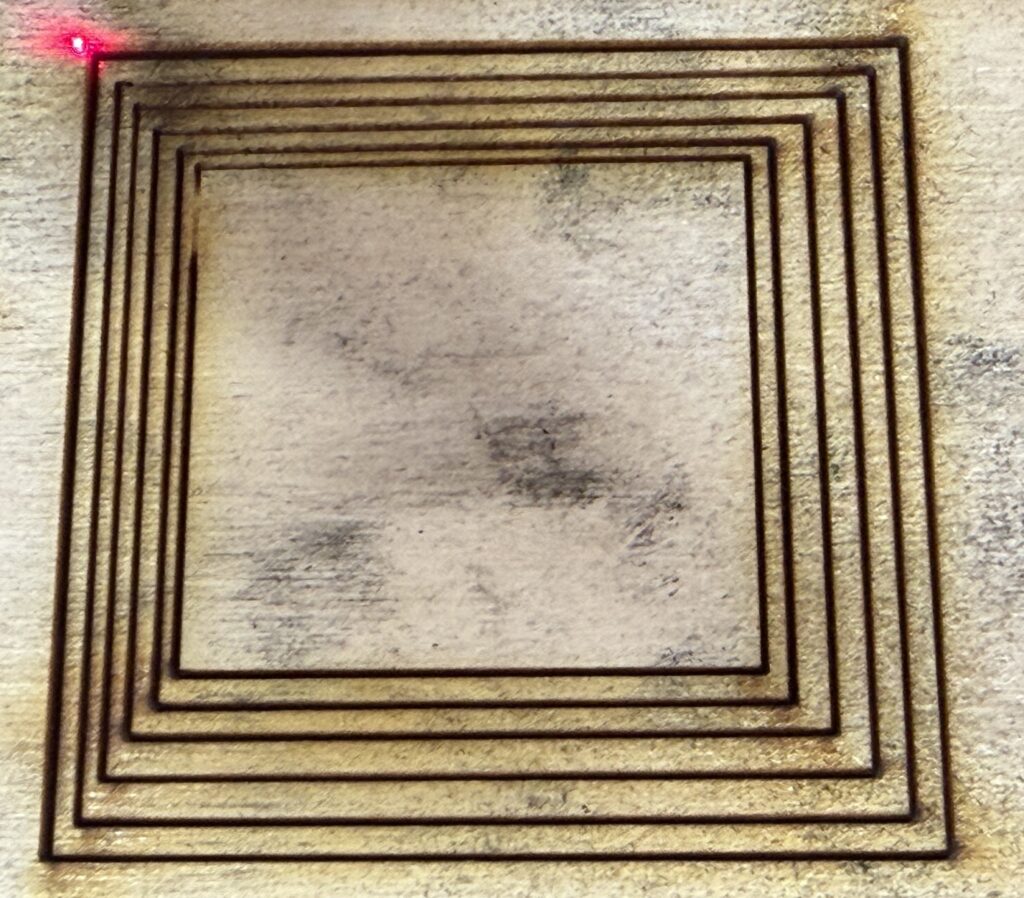
During laser class on June 11, a new weird behavior manifested in the laser lab. The first few millimeters of a cut were skipped. To be more precise, the laser fired at greatly reduced power during this short interval, and then began to fire normally. Here is a photo of a half-inch test square cut while this was happening. The job origin was at the upper left corner and motion proceeded clockwise. You can see that the power was close to normal for a very short time, then greatly reduced for a longer time, then suddenly returned to normal.

We spent a lot of class time trying to figure out what we were doing wrong to cause this problem, but we were not successful. I spent some more time after class, and still could not find any setting or any other user error that could conceivably cause this malfunction.

I tried to characterize it in more detail. Here’s a test where I drew a half-dozen roughly concentric squares and cut it all in one job. Recall that if you draw things inside of other things, all in the same color (“layer” in LightBurn terminology), the program automatically draws the inner ones before the outer ones. So in this case, starting from the red dot at the origin in the upper left corner, the laser first jumps to the nearest corner of the innermost square. Then it chooses a direction somehow, apparently choosing counterclockwise in this case. So, you can see the defect at the top of the left side of the innermost square. The other squares do not show the defect. Each square is a separate cut in that the laser beam turns off and the laser head moves before it turns on again, but the gap between the squares is small. Apparently whatever effect is responsible for the beam working after the initial outage persists between separate cuts, if they are close together.

Here’s a similar test, except that it’s a Fill (raster) layer instead of a Line (vector) layer. The outage appears larger because the linear speed is higher. LightBurn starts at the bottom of Fill layers by default, so the outage appears on the bottom line.

Here’s a variation on the above test. This time it’s a Line (vector) layer again, in fact the drawing is the same file as the nested squares. I broke apart the squares into four lines each, and selected only the top line, using the “Cut Selected Graphics” option to disregard the rest. Then I manually selected the next top line and ran the job again, and so on. In this way I was able to vary the delay between cuts. You can see the outage on all the lines, but the length and strength of the outage varies. I didn’t record the delays, but toward the end of the experiment I was getting better at restarting the job quickly. You can see that a quick restart meant a shorter and weaker outage.

This was starting to feel like some kind of hardware issue, not a logical software or digital issue at all. Thermal, probably, or maybe capacitive. Some process with a long memory and independent of the intended job. I suspected the high voltage power supply, or maybe the laser tube itself, but probably the power supply. I went ahead and ordered a replacement power supply, in case that turned out to be the problem.

Due to other obligations, I was not able to work on this problem before the next scheduled laser class, on June 15. Rather than cancel the class due to the laser malfunction, I decided to go ahead with it and challenge the students to design their jobs to include workarounds for the malfunction. This worked out quite well, I think. Students were flexible and creative in coming up with workarounds for this problem.

Here’s a simple way to cut a half-inch square, with a workaround in the form of a lead-in line. The outage occurs within the lead-in line and the laser operates normally on all the sides of the square. It does tend to waste some material.

To make this work on more complicated designs, you have to understand how LightBurn decides the cut order. If you guess wrong, LightBurn might cut some other segment first, or even schedule a long traverse with the laser off or at very low power, which might cause the outage to recur.

Here’s another way that might save some material.

Maybe Lightburn would choose the isolated segment on the left to start with, and then cut the square in one motion. Maybe not! You can run Preview to find out.

Spoiler: I was right to suspect the power supply. The next article will tell the tale.

LightBurn Updated to 2.1

We’re now running a new version of LightBurn software, version 2.1 or so. The folks at LightBurn Software have added a bunch of new features.

I updated the laser’s computer right before the laser class session yesterday, and we almost immediately ran into some new things. Mostly they were just cosmetic changes, but we did run into something that may be a bug of some consequence. It seems like there might be an error in the translation of old settings into new settings. There seems to be a new feature that involves automatically changing the table height at the beginning of a job. Assuming this is a new feature (I’ve never noticed it before), the value for the height change really ought to be defaulted to zero, so users aren’t surprised by the change. But instead the default had the table rising a fraction of an inch each time. Luckily, one of the students noticed and pointed it out to me, because I was oblivious to the table motion. Until we’re all familiar with any such gotcha features, we all need to be a little extra cautious and maybe spend some time looking at the advanced settings of our jobs before hitting Start.

I haven’t studied the release notes yet, except to see that they’re about 30 pages long, printed out. If you want to get started on absorbing the new features, you can go straight to LightBurn Software’s blog post, here: https://lightburnsoftware.com/blogs/news/lightburn-2-1-quick-nest-enhanced-camera-support-undo-history-and-more

Wiggle Fix Confirmed

I discovered I could just push the bearing back up into its plastic fitting. It’s pretty snug, but it might work its way out again. If it does, we can try an adhesive or re-engineering the fitting.

Tests with the standard half-inch squares show that this does fix the problem. No more wiggles!

I recommend checking the bearings before doing any critical laser jobs. Just lower the table a few inches to reveal the tops of the threaded rods. If all four bearings are fully enclosed in their plastic fittings, that’s good. If not, you can push the bearings up into the fittings. If that’s needed, please let me know so I can consider a more permanent solution.

Likely Cause of “The Wiggle” Found

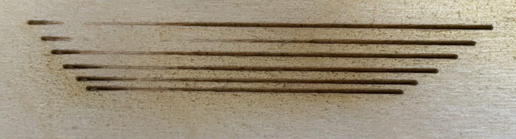
For at least the last few months, and possibly since the laser was moved to the current Colab 3.0 location, we’ve seen a slight wiggle in certain lines that should have been straight. The problem often surfaced in laser class. My standard class demonstration job is to cut out a half-inch square from 3mm baltic birch plywood. We’d see a slight wave in the bottom side of the square. Changing the size of the square would change the size of the wiggle, often eliminating the visible effect completely. Occasionally other users would report much more severe wiggle effects in particular jobs.

This image shows the sheet of baltic birch plywood from which a test square was cut. You can clearly see the wiggle along the bottom edge.

I believed this to be some sort of mechanical problem with the laser. Specifically, it seemed like it had to be something that was loose that should have been tight. The things I had checked before today seemed to be fine. Today I had some free time in the neighborhood of Colab, so I made a concerted effort to check everything that could be involved, and I think I now know what the problem is. I don’t know the exact repair procedure yet, but I’m confident it will be repairable.

The problem is in the table mechanism. As you probably know, our machine focuses the laser beam onto the work material by raising or lowering the table, while the laser tube, mirrors, and focusing lens all stay at their fixed heights. You might not be familiar with the mechanism that raises and lowers the table. There are four vertical threaded rods, one near each corner of the table. A stepper motor drives a toothed belt near the floor on the left side of the machine, and that toothed belt rotates the threaded rods on the left front and left rear corners. Another stepper motor and belt does the same for the threaded rods on the right side. A matching nut is fitted to each rod, and connected to the table, so that rotation of the rods is converted into vertical motion of each corner of the table. Both stepper motors move in sync, so that all four threaded rods rotate the same amount whenever the table is to move up or down. Thus the table stays level while moving up or down.

If any of the rods ever get out of sync with the others, the table will be tilted or even twisted, and manual intervention is required to realign the table. This happens rarely, and only when some mechanical blockage prevents one or more corners of the table from moving up or down. In that case, the stepper motor on the blocked side stalls and/or the toothed belt skips one or more teeth. This failure is noisy and hard to ignore. It has happened a few times, but as far as I know it has not happened since the laser was moved out of the original Colab 1.0 location. I’d remember, because the table realignment procedure is a huge hassle.

None of that has anything directly to do with the wiggle, which is an unwanted motion in the Y axis (front to back) and not obviously related to the Z axis (up and down) motion of the table.

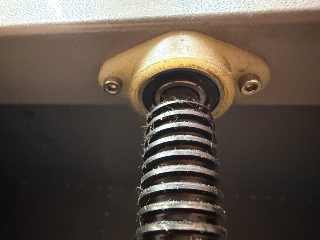
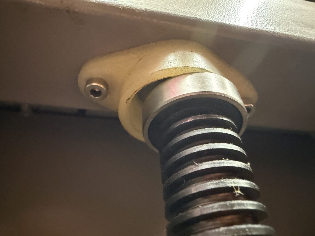
Those threaded rods have to stay vertical to do their job, and they have to be free to rotate. So, there’s a bearing at the bottom end of each rod, connected to the floor of the chassis, and another bearing at the top end of each rod, connected to the underside of a horizontal chassis plate near the midline of the chassis. The weight of the table bears down on the bottom bearing, which is supported by the sturdy bottom of the chassis, and has nowhere to go. The weight also pulls down on the top bearing, which is dangling from the bottom of a panel, held in place by a plastic fitting and two screws that connect the plastic fitting to the panel. I suspect the top bearing is merely friction-fitted into the plastic fitting.

As you can see from these pictures of the left-front and right-front threaded rods, the bearing at the top of the right-front threaded rod has escaped from its plastic fitting. The same is true of the right-rear threaded rod. This is not an immediate catastrophe, because the four nuts connected to the moving table also provide some vertical alignment for the threaded rods. The right rods don’t just fall over. However, they are no longer held rigidly vertical. The tops of the right side rods are free to move a little in the Y axis, moving the table and flexing some other components that are nominally rigid.

But why would they move at all? Shouldn’t they just stay put in their intended vertical orientations? There’s no side force being exerted on the table, after all. Or is there? If you’ve ever put a hand on the laser chassis while it’s running a job, you know that it shakes a little. The substantial mass of the moving gantry, and to a lesser extent the mass of the moving head, creates a reaction force that moves the whole chassis whenever the gantry or head accelerates or decelerates. This is made worse by the fact that we usually leave the chassis sitting on its wheels, instead of deploying the leveling feet to make it sit square on the floor. The chassis (and thus the gantry and the head and the mirrors and the lens) shake relative to the table. Because the moving mass is mainly due to the moving gantry, the shake is mainly in the Y axis, and it only happens for a short time after the gantry has started or stopped suddenly.

This explains what we see with a half-inch test square. I almost always use the left-rear corner as the job origin point. That means the head is initially stationary and positioned over the left-rear corner of the square. When the job starts, the head moves to the right (in the X axis). It accelerates, then (maybe) runs briefly at the designated speed (45 mm/sec in this test) and then decelerates to zero again at the right-rear corner. This is only a motion of the head, though, and in the less-flexible axis of the mechanism, so this doesn’t cause a noticeable shake. Next is a right turn: the heavy gantry starts to move, accelerating forward and then decelerating back to zero. This is relatively straight, but shakes the machine. So after the next right turn, the gantry is stationary relative to the chassis but the table is shaking a little in the Y axis while the head accelerates to the left and decelerates to a stop at the front left corner of the square. That makes the bottom edge of the square a little wiggly! And only the bottom edge.

I tried another test to confirm the theory. I wedged pieces of scrap material between the edge of the honeycomb mesh table and the nearby chassis edges, discouraging the table from moving relative to the chassis. I re-ran the test, and the visible wiggle was gone. We can’t leave it wedged, though, because that would also prevent focusing.

I wanted to know how it was possible that the top bearings had escaped from their plastic fittings. The fittings seem undamaged. It seems like either the threaded rod plus bearing assemblies had gotten shorter by about a quarter inch, or else the distance between the bottom of the chassis and the midline panel of the chassis had grown by the same amount. Perhaps the chassis had gotten bent somehow, maybe during moving between Colab locations. I used a handy tape measure to investigate, and found that the chassis was pretty much the same dimensions on both sides. So the theory has to be that the rod assemblies got shorter.

I’m guessing that the bearing was friction-fitted onto the rod, and that it simply slipped down onto the rod somehow. That matches what the photos above show. However, at that point I was out of time and had to put the laser back together rather than tear it apart to find out how the rod assemblies were built. That part of the investigation, and the formulation of a repair plan, will have to wait for another day.

How to Reserve Time on the Laser

We are still working toward a mostly-online system of reserving time to use the laser. And, I still don’t know when that system will be ready.

In the meantime, the way to get time on the laser is to send your desired date(s) and time(s) to Vic, who can be reached by DM on the sdcapgroup Slack workspace as @Jolly Rancher, or by email at jollyrancher@sdcolab.org. Vic is a busy person and also a volunteer, so please be patient and friendly.

Reminder: you must have completed the Basic Operation and Safety class on the laser before you can reserve time on the laser. If you took the class before Covid at the original Colab location, you’ll need a refresher. For the moment, that means retaking the BOS class. If you’d rather wait until we can offer an abbreviated refresher course, please let me know. I won’t be developing the refresher course unless I hear about some demand for it.

U Axis Stepper Motor Driver Installation

On April 24 I completed the physical and electrical installation of an additional stepper motor driver in the laser. This type of device sits between the Ruida laser controller and the actual stepper motor that mechanically drives the various axes of the machinery. The new one adds support for the U axis, in addition to the existing X, Y, and Z axes.

The idea is that this will better support the use of rotary adapters with Lightburn software. This theory has yet to be proven.

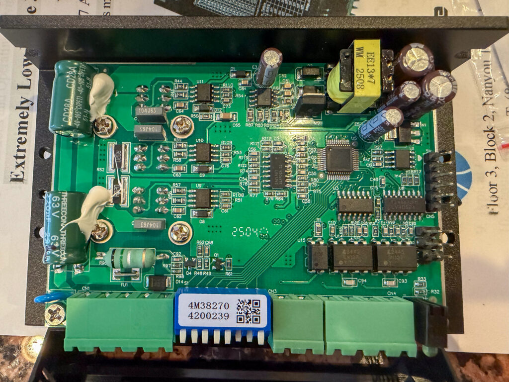
Here is what the new Leadshine 3DM583 stepper motor driver look like on the inside. It’s more complex than I expected. It’s the current version of the 3ND583 driver that is used in the existing X and Y axes.

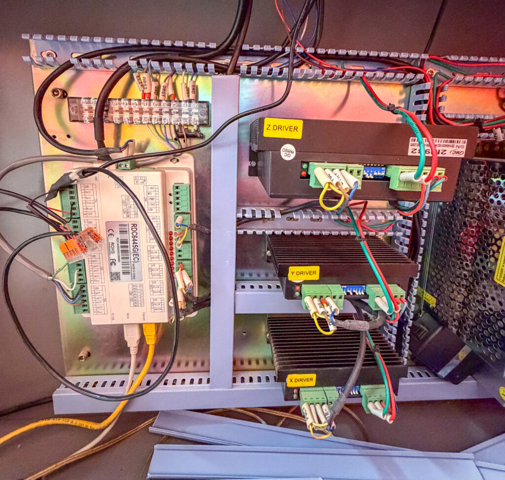
And here is a view of the electronics inside the laser, before the addition of the new driver. The off-white box on the left is the Ruida laser controller. The three black boxes in the middle are the existing stepper drivers, for the X, Y, and Z axes. The shiny perforated-metal box on the right edge is one of several power supplies. The new driver will be squeezed in above the Z axis driver.

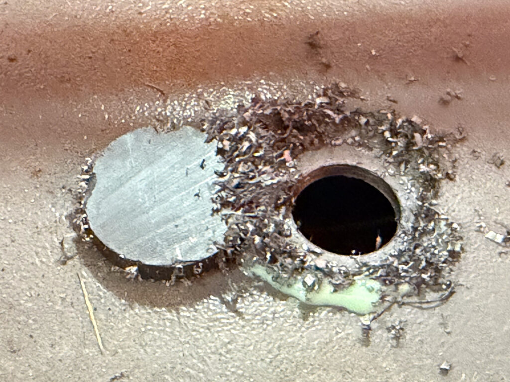
The biggest challenge mechanically was creating this 16mm hole in the chassis to mount the connector for attaching either of our two rotary adapters to the new driver. This was a fine excuse to acquire a new tool, so I picked up a set of annular cutters. There’s just room to use one of these with a small battery-powered hand drill, and it did a fine job of making a hole in the heavy sheet steel of the laser chassis. To the left of the hole there’s a magnet, which I used to help keep the tiny chips of metal from going all over the place. The light green material is a metal cutting fluid called Anchorlube.

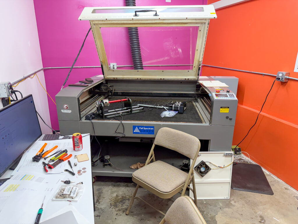
And here’s what the room looked like after an afternoon and evening of messing around. The electronics area is accessed through the doors on the right side, next to the orange wall. There isn’t a lot of extra room around the laser for service! Both of the rotary adapters can be seen on the laser’s bed. On the desk is a mix of tools that belong in the laser room, tools I brought from home, and tools I scrounged from other parts of Colab.

I performed only preliminary basic tests to confirm the installation. I’m able to rotate either rotary adapter using the U+ and U- buttons on the controller keypad, which proves that the electrical connections are basically working. However, it didn’t behave the way I expected. All the other axis motion buttons cause the corresponding motor to run while the button is held down. The new U axis, however, continues to move after the button is released, and only stops when another button is pressed. I expect there’s a setting for that, but I didn’t find it before quitting for the day.

Laser Classes Update

Sessions of the Basic Operation and Safety class for the laser are continuing at an accelerated pace: 4 sessions in March, 6 in April. I’ll try to keep this up as long as there is demand.

For now we are going to try to stick to a schedule for scheduling new classes. Specifically, new classes will be added once per calendar month, sometime during the last week of the preceding month. Classes might still be added or changed at any time, but most new classes will be posted in a single batch during the last week of the month before they occur. The purpose of this schedule is to limit the number of volunteer hours needed just to maintain the schedule.

I’ve always preferred that the BOS classes be free, because they’re essential to the use of the laser and we do want people to use the laser. However, we’ve found that the number of people who sign up for the free class and then fail to show up is unacceptably high, given the high demand for the BOS class. So for the moment we’re charging a nominal fee of $10 per student, in the hope that this will discourage people from skipping out on a class reservation. If this doesn’t work, we’ll have to resort to drastic measures, like making people pinky-swear that they will show up for class.

Rotary Adapter Workshop

On April 12 we had a scheduled workshop session in the laser room with the goal of setting up and calibrating the two rotary adapters for use with the laser in its “new” configuration, and creating a set of simple procedures for laser users to follow in order to use one of the rotary adapters. I was joined by Kip, Guy, Renee, and Sriram, who were all very helpful in trying to figure things out.

A rotary adapter replaces the Y-axis motion of the gantry with rotary motion of the work piece, enabling the laser to work on a cylindrical or conical object. This has always meant unplugging the gantry and plugging in the rotary adapter in the same place. That’s what the original laser controller expected, and it worked fine. Enabling the rotary adapter with the old software just meant a different setting for calibrating the Y axis.

As best we could figure out at the workshop, this doesn’t work as expected with the new controller. If we enable the rotary adapter, the job can’t be started by pressing the Start button, as is our standard procedure. If we instead used the Send button and then started the job from the laser’s control panel, the job would try to run, but there would be no motion on the rotary axis. This despite the fact that jogging the position manually in the Y axis did correctly cause the rotary adapter to spin. We only figured out that much by reading forum posts online.

We were able to get a rotary job to run with both axes, but only by turning off the switch in Lightburn that enables the rotary adapter. So, as far as Lightburn and the Ruida controller were concerned, it was just running a normal flat job on the bed. Of course, the Y axis calibration was used instead of any rotary axis calibration. If we wanted to use this as the standard procedure for rotary jobs, we’d have to ask the user to change the calibration setting, and then remember to change it back after the rotary job is completed. This seems inconvenient and error-prone, and risks exposing a beginner laser user to extra complexity needed only by users of the rotary adapter. This would probably be unacceptable, especially given that we’ve gotten by this long without the rotary adapters being commonly used.

Our best guess is that we need to connect the rotary adapter to the Ruida controller’s “U” axis, which is currently unconnected. In order to do that, we’ll need to install a fourth stepper motor controller (in addition to the existing X, Y, and Z axis controllers). I have that stepper motor controller on order.

It’s also possible that there are controller settings and/or Lightburn software settings that need to be adjusted in order to make it work with the old method (unplugging the gantry and plugging the rotary adapter into the Y axis controller). If so, I’d think we would have learned about those settings from the forum threads we read, but we did not.

The five of us will get together for a followup workshop once the new controller has arrived.

Progress on Camera Installation

Work is underway to add a camera to our laser. The camera will be installed on the underside of the laser’s lid, looking down onto the bed. After you’ve placed your material on the work bed of the laser, you’ll click the camera icon. This will take a snapshot of the bed with the material placed, and make that snapshot the background in the drawing area of the Lightburn software. It will then be easy to draw your design right on the image of your material, without having to fiddle around with aligning your material with your drawing. This has proven to be a nice convenience on newer model lasers that come equipped with a camera, so we can expect it to be helpful when added to our laser, which is now almost twelve years old.

For this to work well, the camera has to be in the exact same 3-dimensional position every time it’s used as when it was installed and calibrated. Our laser’s lid wasn’t originally designed with this requirement in mind, so I’ve made some modifications. Our laser already has an upgraded hinge, because the original hinges kept breaking. I replaced the four tiny cast aluminum (!) hinges with a beefy steel piano hinge running the full width of the lid. This hinge has very little mechanical play, so the camera’s X axis is well defined, as is the distance from the hinge pin to the camera. That just leaves the angle of tilt of the lid when it’s open.

The lid has pneumatic lifters, one on each side. These make it much easier to lift the heavy lid, and they keep the lid up after you’ve lifted it. However, the lifters get tired over months and years of use, and the open angle of the lid begins to droop. My idea for coping with this problem is to add cables, one on each side of the lid, that constrain exactly how high the lid can be opened. The pneumatic lifters will push against the cables to reach the same maximum height every time.

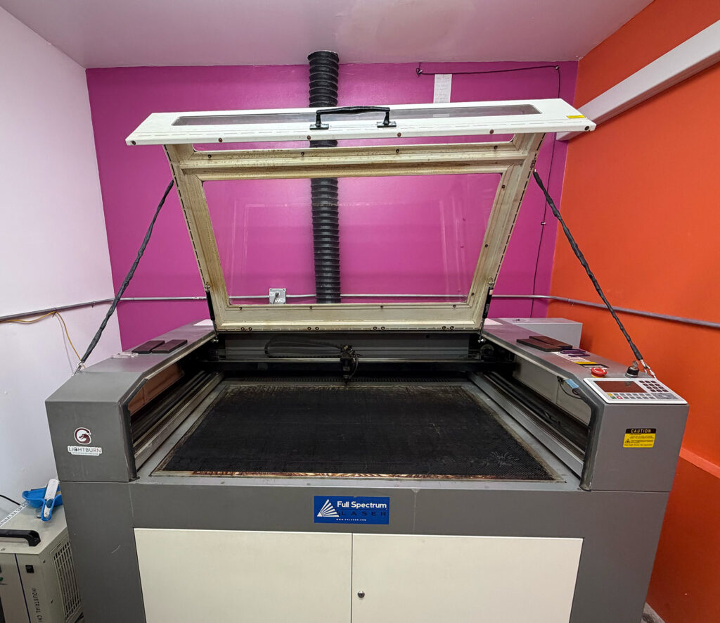
The cables are made out of eighth-inch stainless steel wire rope, with standard hardware, including a turnbuckle to allow each cable to be adjusted in length. Because the wire rope has sharp ends in multiple places, I’ve encased the wire rope and most of its hardware in a protective plastic sheath. A carabiner at each cable end then clips to a screw eye installed in the lid or chassis. Here’s what that looks like today:

Camera installation and calibration will be the next step.