Cutting Acrylic in Two Passes

As a test I was cutting an array of five-pointed stars about 3/4″ in diameter out of quarter-inch acrylic. It took about 60 speed and 100 power to cut the outline of the stars all the way through the acrylic, but they remained connected to the sheet at the sharp corners. Even at 40 speed, they had to be mechanically punched out, and the points were rough. The whole area of the material was quite warm at the end of the job. I’m thinking the sharp points were rewelding to the sheet after the cut.

As an experiment I tried cutting at 80 speed, but with the number of passes in the vector settings table set to 2. That should be effectively about the same power and about the same overall duration as cutting at 40 speed. Sure enough, the results were pretty similar. The stars were still stuck in the sheet by their corners. With passes set to 2, each individual star is cut out twice before moving to the next one. There’s no delay between the two passes. For a small job like a single star, there’s not much benefit in dividing the power up into two passes.

Then I changed the passes setting back to 1, and ran the whole job twice. That’s the same effective power delivered as setting passes to 2 and running the job once, but it gives each cut time to cool down between the two doses of heat. The result was much better. The stars dropped out of the sheet (with a bit of shaking) and their points were pretty clean.

Consider using this trick if you run into rewelding on sharp corners when cutting thick acrylic.

Power Back To Normal?

Today I went in to try and diagnose the problem with reduced power. Well, the problem is gone, but I didn’t do anything to fix it.

My hopeful theory was that the surge suppressors inside the high voltage power supply were starting to fail again. That’d be a cheap and easy repair. I opened up the high voltage power supply and found no visible damage to the surge suppressors, and they tested good with a multimeter (now in the toolbox for future use).

The power faded out during a class session, where we were running small jobs with longish pauses in between. It was a warm day, but far from the warmest we’ve had to deal with this year. Today I tried running several longish jobs at high power to stress the system, but couldn’t get it to misbehave.

Terry ran some quarter-inch acrylic cuts last night and also got normal performance (60 speed and 100 power to cut through).

So, I don’t know what was wrong, or whether it will be wrong again anytime soon.

Reduced Power Output

Toward the end of class yesterday we noted that the laser output power wasn’t up to par. Material that can usually be cut at 20% power was requiring 70%. Alignment test pulses were weaker than usual, even before passing through any optics.

That leaves the laser tube itself and the electronics. I’m hoping this is the same problem we had before, which turned out to be failing surge suppressors inside the high voltage power supply. If so, that’s a cheap and easy fix. If not, we may have an expensive repair to do.

In the meantime, as far as I know it’s OK to use the laser by just cranking up the power settings (or reducing speed). Be aware, though, that it’s likely to get worse or fail entirely.

Cermark Test

After talking about Cermark from Thermark (now Ferro) in laser classes for two years, I finally got around to trying it. I sprayed a light coat of Cermark LMM-6000 from an aerosol can onto a few small galvanized steel plates (Strong-Tie TP35 from Home Depot) I had left over from another project. After it dried, I engraved using the laser at various settings, both raster and vector, and then washed off the rest of the spray with water.

Initial test of Cermark LMM-6000 on galvanized steel plate

Initial test of Cermark LMM-6000 on galvanized steel plate

The sun images are about 0.75 inches in diameter; the whole plate is 3.25 inches wide. The top raster image of a filled sun, a lines-only sun, and the word “Colaser” was engraved at 100% speed and 100% power. Some of the fine detail in the cutouts is filled in, so that setting is too high. The lower raster image was engraved at 50% power, and it looks pretty good. A third raster test was done at 10% power, and it made no mark on the metal at all.

The vector test image was the text “coLaser.org”. The topmost one was done with the wrong art, so each stroke was double-cut or worse. Disregard that one. The test right below it was cut as single lines at vector settings of 100% speed and 100% power. The middle test was done at 20% power, and the bottom test was done at 5% power. All three tests look pretty good. The resulting line is just a little bit narrower at the lower power settings. Even lower power settings would be worth experimenting with.

You can see some dropouts near the top of the top sun image. I think that’s due to inadequate spray coverage. The instructions say to make a thin coating that just covers the metal. I may have been a little stingy with the spray.

The photography was a bit challenging. Depending on lighting, the mark can be nearly invisible in photos. In person, though, it looks like black on top of the metal.

The marking seems to be quite durable. It’s a bit rough to the touch, and if it were ordinary paint it would rub off easily. As a test, I tried to scrape it off with my thumbnail. That worked like a nail file: the Cermark ground down my thumbnail and took no damage. An Xacto knife was able to scrape it off. In between, scraping at it with a piece of copper was more or less a draw: some Cermark was removed, but some copper was left behind too.

There was no visible smoke or ash from the engraving, so I suppose this material is completely safe for the laser. The engraved image is visible before washing, but the appearance is not a good guide to laser power settings. The third row of raster tests looked black before washing, but did not stick to the metal. (I was in a hurry and neglected to take any photographs before washing.)

Thermark has recommended settings for this material for 30 watt and 45 watt CO2 lasers. They talk about speed in inches per second, and I don’t know offhand how that translates to the percentage speed settings we use on Retina Engrave 3D. For the 30W laser, they recommend maximum power for most materials, but on the 45W laser they suggest using lower settings for some materials. On galvanized steel, they still suggest full power at 45 watts. They don’t give any suggestions for 150W lasers like ours.

Also, note that the laser may not have been working at full power the day I ran this test. During the class later that day, the laser power was dropping significantly (for reasons yet to be determined). In any case, you’ll need to run tests with your material to determine the best settings for Cermark.

We also have a spray can of Cermark LMM-6044, which is for glass and tile. I still have yet to try that.

September Classes

Three new sessions of the basic operation and safety training course have been scheduled:

Thursday, September 15, 6pm to 10pm

OR

Sunday, September 18, 1pm to 5pm

OR

Sunday, September 25, 1pm to 5pm

If you’d like to sign up for one of these classes, please email class@colaser.org and let me know which session you’d prefer. The laser room is small, so class size is limited.

The class is free, and once you’ve completed the class you’ll be able to schedule time to use the Colaser, which is also free for art and personal projects. You don’t need to bring anything special to class. Be prepared for about 90 minutes of classroom instruction, followed by hands-on exercises with the laser.

Laser Cutting Out of Square

I tried to build a nice box out of laser cut parts, and found that rectangles weren’t coming out rectangular!

It was off by about 0.38 degrees, or 5/16 inch across the whole bed. That’s a lot! Or not, depending on what you’re trying to make.

IMG_5576

I went back and measured some other things with square corners that have been cut on Colaser. Ones from about a year ago are square, but more recent ones are not. This problem has been happening for months.

At first glance, this kind of error seems impossible. The designs in question are perfect rectangles, and they are aligned with the machine’s axes, so nothing subtle like slippage in the stepper motors would account for it. The cut sides would have to be perfectly parallel to the Y rails that the gantry moves on and the top and bottom would have to be perfectly parallel to the X rail on the gantry. I think this means the gantry itself must be out of square with the side rails.

I failed to find anything on the internet about this problem on our exact model of laser, but I did find a case where a smaller model from the same company had the same symptom. That smaller model is very different mechanically, but the relevant part of the mechanism is similar. There’s a shaft connecting the left rail drive belt pulley to the right rail drive belt pulley, and a coupler in the shaft. If either half of the shaft slips in the coupler or in its respective belt drive pulley, two belts become misaligned, and so the gantry is no longer perpendicular to the Y axis. Yes, that’s right, another alignment adjustment that I knew nothing about.

With some help from Robert, whose reserved laser time I horned in on, I was able to get this readjusted. I chose to adjust it at the coupler, since I couldn’t be sure the pulleys weren’t fixed into a particular position on the shaft by flats ground into the shaft. I loaded up a big sheet of cardboard onto the bed, set the power very low, and engraved a long horizontal line and a long vertical line, to match my 16×24 inch carpenter’s square. I set the square carefully on the vertical (Y axis) line, and measured the deviation of the horizontal (X axis) line. Scaled to match the full width of the bed, that is the amount of correction needed on one belt or the other.

The easiest way to adjust the alignment is to leave the machine turned on, so that the stepper motor holds the left half of the shaft from rotating. Then loosen the set screws on that half of the coupler, turn the coupler the appropriate amount, and retighten the set screws. The stepper motor is not so strong that it can’t be shifted, so some care is needed to avoid applying too much force to the fixed half of the shaft. The whole procedure requires care, for that matter, since the coupler is under and behind the fragile, expensive glass laser tube.

The easiest way to keep track of how far the belt has moved is to use the red laser dot, with the head as close to the side being adjusted as possible. We marked the cardboard with the utility knife, which makes a finer mark than any pen or pencil we had handy. Then we offset the laser dot by the amount we calculated it needed to move. Then Robert watched the laser dot while I rotated the coupler until the dot was again on top of the mark. Having two people makes this procedure much easier.

It still took us six tries and two or three hours to get it right, since we had to invent the procedure. Another thing that makes it take a while is that Mirror 2 needs to be readjusted after every adjustment of the gantry alignment.

At one point we had the gantry pretty far out of alignment, with the right side of the gantry closer to the front of the machine. When we tried to home the machine in this state, it hit the mechanical stop on the left side before it hit the limit switch on the right side. That means it made a horrendous noise (either the belt repeatedly jumping a tooth or the stepper motor repeatedly slamming against the stop, I couldn’t tell which) until the homing procedure was aborted.

Just to be clear, I’m not suggesting that regular laser users should attempt this procedure, or really any of the alignment procedures. I’m just documenting it here for reference by me or future laser technicians, and for general interest. As a user of the laser, it’s useful for you to be aware of what sorts of things can go out of adjustment, so you can be on the lookout for them. Now we know that if you are cutting parts that need to fit together precisely, it might be a good idea to verify that the X and Y axes are really perpendicular before you commit a lot of time or material.

So, how did this happen? I don’t know. All the set screws were nice and tight. The only thing I can figure is that somebody crashed the head hard in the Y axis and something slipped, despite being tight. If you do have a head crash, please let me know so I can check for alignment issues.

New Exhaust Fan

The roof-mounted exhaust fan that pulls the smoke out of the laser chamber has been getting weaker recently. A cursory inspection revealed no problems with the ducting, and power getting to the blower, so the blower itself was to blame.

I procured a new, more powerful blower and Natural installed it on the roof on August 27. The new blower exhausts smoke more quickly than the old one ever did.

img_5553

Once the old blower was out of the system, the problem became apparent: the intake of the fan was almost totally clogged up with soot from all the smoke we’ve generated over the last two years.

IMG_5558

With a half a gallon of Krud Kutter, I was able to clean off the bulk of the soot and verify that the old blower still works fine. So now we have a backup blower in reserve, and we know that cleaning the blower is a regular maintenance item we need to take care of.

img_5575

Learning about Alignment

It turns out there’s more to laser alignment than I thought, and more than is revealed in the written instructions or in the alignment procedure video.

XY Plane DiagramThe basic alignment involves adjusting the three mirrors, shown here as M1, M2, and M3. The gantry carries M2 and M3 forward and backward along the Y axis of the machine. M3 travels left and right with the head, along the gantry in the X axis of the machine, and reflects the beam down onto the work. The infrared cutting beam comes out of the laser tube, passes unchanged through the beam combiner (BC), and bounces off M1, M2, and M3. The red laser is reflected by the beam combiner, and travels with the cutting beam as it bounces off the mirrors.

M3 closeup
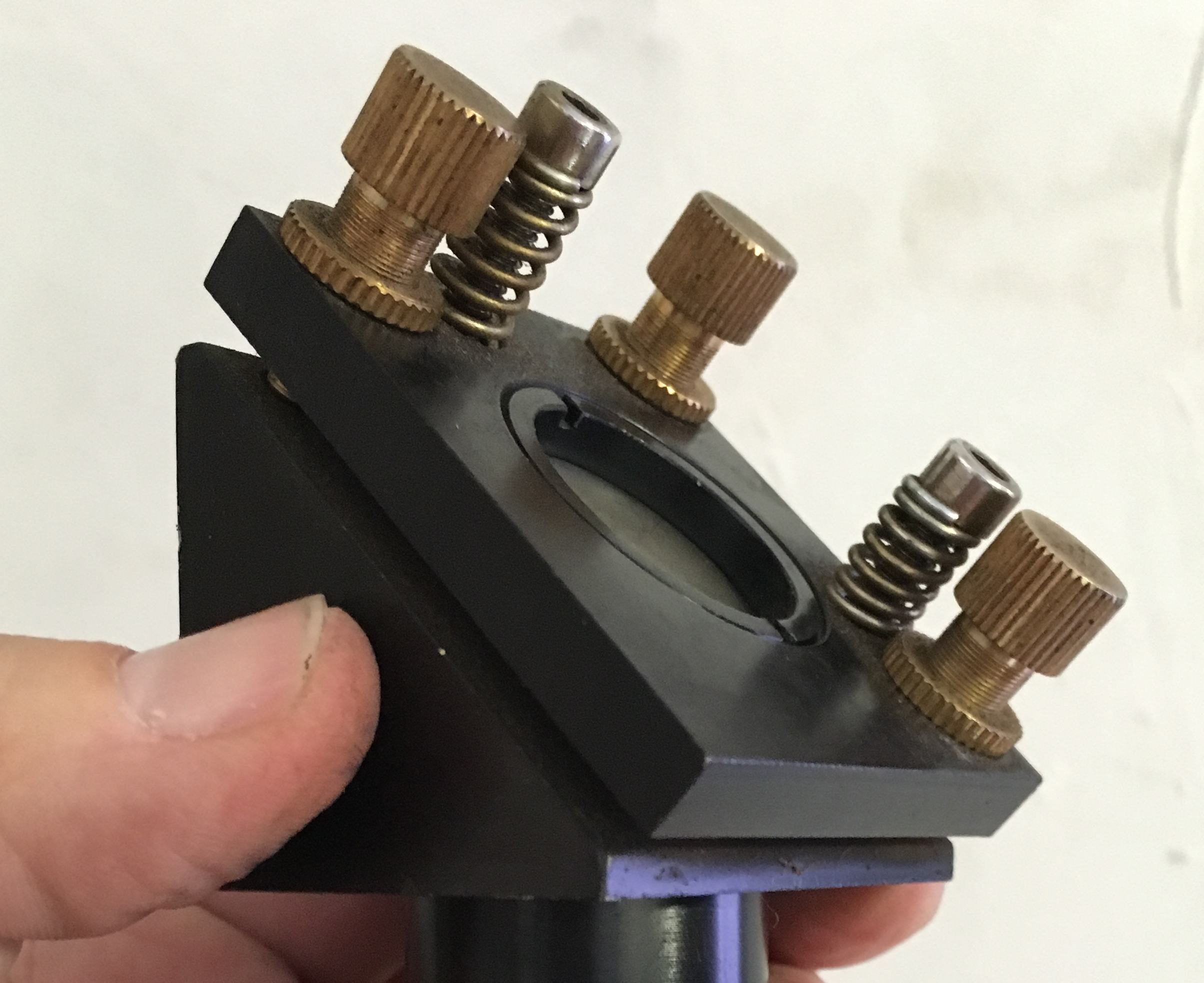
Each mirror floats in a mount like the one shown here. The three thumbscrews, pushing against the tension springs, define the position and orientation of the mirror carrier on its mount. By turning one or two of the thumbscrews, you can tilt the mirror over a pretty wide range. By turning all three, you can move the mirror a little, without changing its angle.

In the basic alignment, the first goal is to arrange for the beam to leave M3 at the same place and at the same angle, regardless of the position of the gantry (that is, the Y axis) or the position of the head on the gantry (the X axis). The only way this can work is if the beam between M1 and M2 is exactly parallel to the Y axis, and the beam between M2 and M3 is exactly parallel to the X axis. Luckily, these two constraints don’t interact. We first measure where the beam hits M2, and adjust the angle of M1 so that it doesn’t move when the gantry moves. Once that’s perfect, we measure where the beam hits M3, and adjust the angle of M2 so that it doesn’t move when the head moves on the gantry.

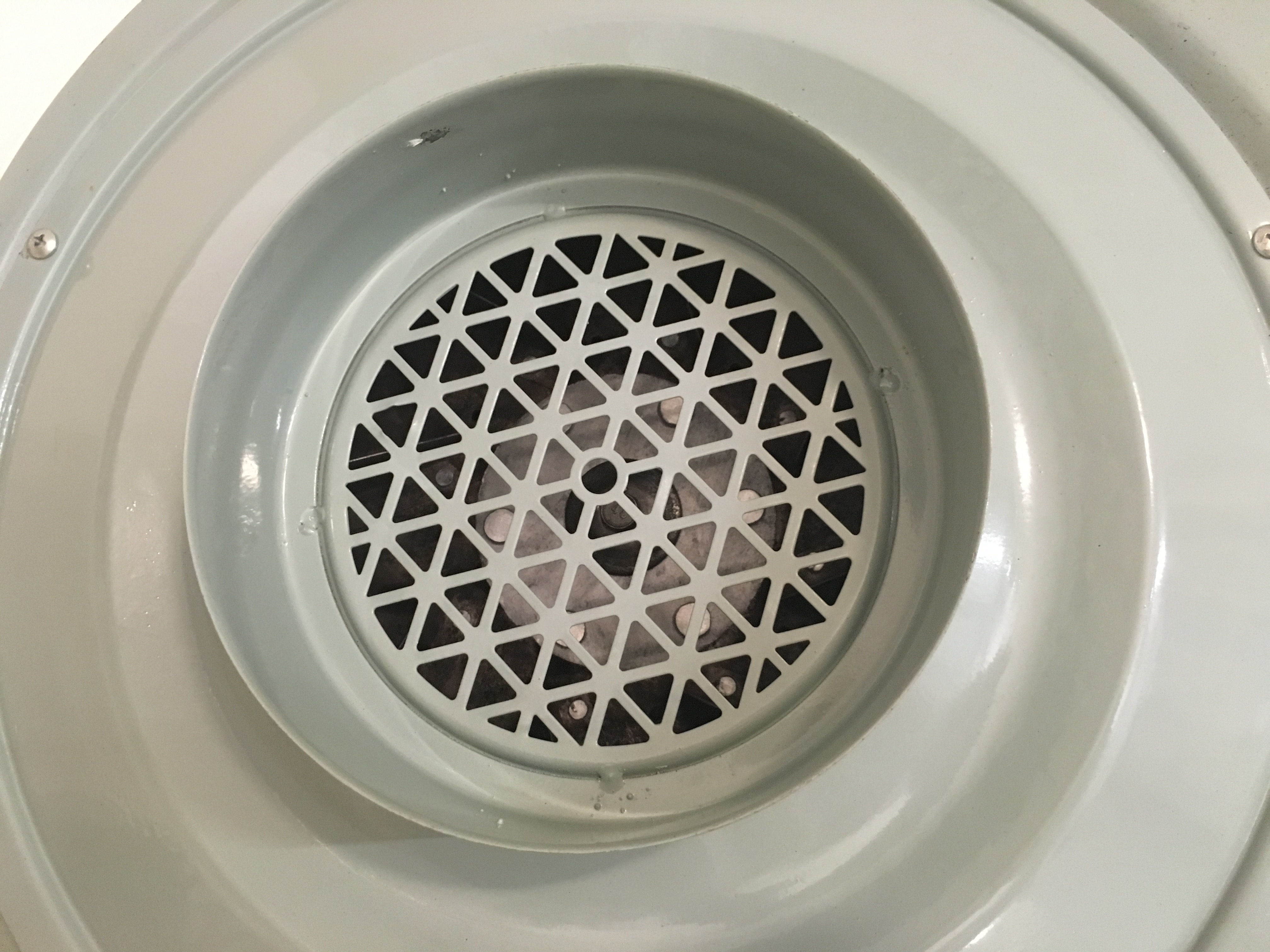
Now that we have the beam hitting M3 consistently, the final step of the basic alignment is to adjust M3. We want the beam reflected from M3 to be vertical and centered on the lens. The lens is buried inside the head, so it’s not easy to measure where on the lens the beam is striking. If we pull the lens tube out of the head, we can measure where the beam falls on the table without the lens. Now we have the same type of adjustment to make as before: we adjust M3 so that the beam hits the table in the same place, regardless of the Z-axis height of the table. That guarantees us a consistent vertical beam.

That’s great. We have a nice vertical beam that doesn’t move around when the mechanical axes move, so we can cut or engrave consistently anywhere on the work. But we haven’t yet arranged for the beam to hit the center of the lens. If that nice vertical beam hits the lens off-center, it will come out of the lens at an angle. The beam has to pass through a relatively small nozzle at the bottom of the head, and that nozzle can’t be moved from the central axis of the head. If the beam is at any significant angle from vertical, it won’t go through the nozzle cleanly. Not good!

So what controls where the beam strikes the lens? It can’t be the tilt of any of the mirrors, because those angles are already fully constrained by the alignment we just completed. M1 has to be set to make the M1-M2 beam parallel with Y, M2 has to be set to make the M2-M3 beam parallel with X, and M3 has to be set to make the M3-Lens beam vertical. What’s left? We need to find two degrees of freedom somewhere, to adjust the beam position at the lens to the center, without disrupting the beam angles. These adjustments are not covered in the basic alignment procedure.

The beam position can be adjusted along the Y axis by shifting the position of M2. This is done by loosening the mounting bolts at the base of the M2 mounting pillar and sliding the whole pillar forward or backward. This is possible because the mounting holes are slotted.

The other axis we need to adjust is the Z axis, or height of the XY plane the beam travels in from the laser tube to M3. The only way to adjust this height is to change the physical height of the laser tube itself. The tube is mounted on two stanchions, each of which telescopes with a sliding dovetail arrangement. We must loosen the set screws on the dovetail, slide the upper part of the stanchion to a new height, and retighten the set screws.

When we’re adjusting the beam position, how do we measure it? Ideally we’d be looking at where the beam falls on the lens itself, but that’s hard, because the lens is inaccessible inside its mounting tube. I’ve come up with two procedures that can be used as a substitute. The easier procedure is to simply measure where the beam enters the head on the way in to M3. There’s a nice circular opening in a vertical plane machined into the head. If the head is designed in the obvious way you’d expect, the beam should pass through the center of that opening. As far as I can tell, this is good enough.

An alternative procedure is to remove the lens and try to measure the beam position as it exits the head, after it would have passed through the lens. One way to do that is to place a thick object on the table and raise the table so the top of the object just touches the bottom of the nozzle. Trace around the nozzle onto the object, then remove the lens tube. Then we just need to center the beam inside the traced circle.

This all assumes that the lens is symmetrical and that it is mounted horizontally, perfectly perpendicular to the Z axis travel of the table. We’re probably safe to assume that the lens is ground symmetrically, but the little silicone (?) gasket between the lens and its holder adds some uncertainty in its exact orientation. One test we can easily do is loosen the nut that holds the lens tube in place, just enough so it is free to turn about the optical axis. As we spin the lens tube, ideally the beam should not move. In practice, it does move a little bit. As long as the beam stays close enough to center to pass cleanly through the nozzle, it should work fine.

Another check is to repeat the check where we move the Z axis (table height) up and down and watch for the spot on the table to move, this time with the lens in place. If the spot doesn’t move with or without the lens, we know it’s passing through the exact center of the lens. Again, in practice it’s enough if the beam passes cleanly through the nozzle.

So, a proper optical alignment goes beyond adjusting the nice golden thumbscrews on the three mirrors. The other two adjustments must be used to center the beam on the lens and make it vertical.

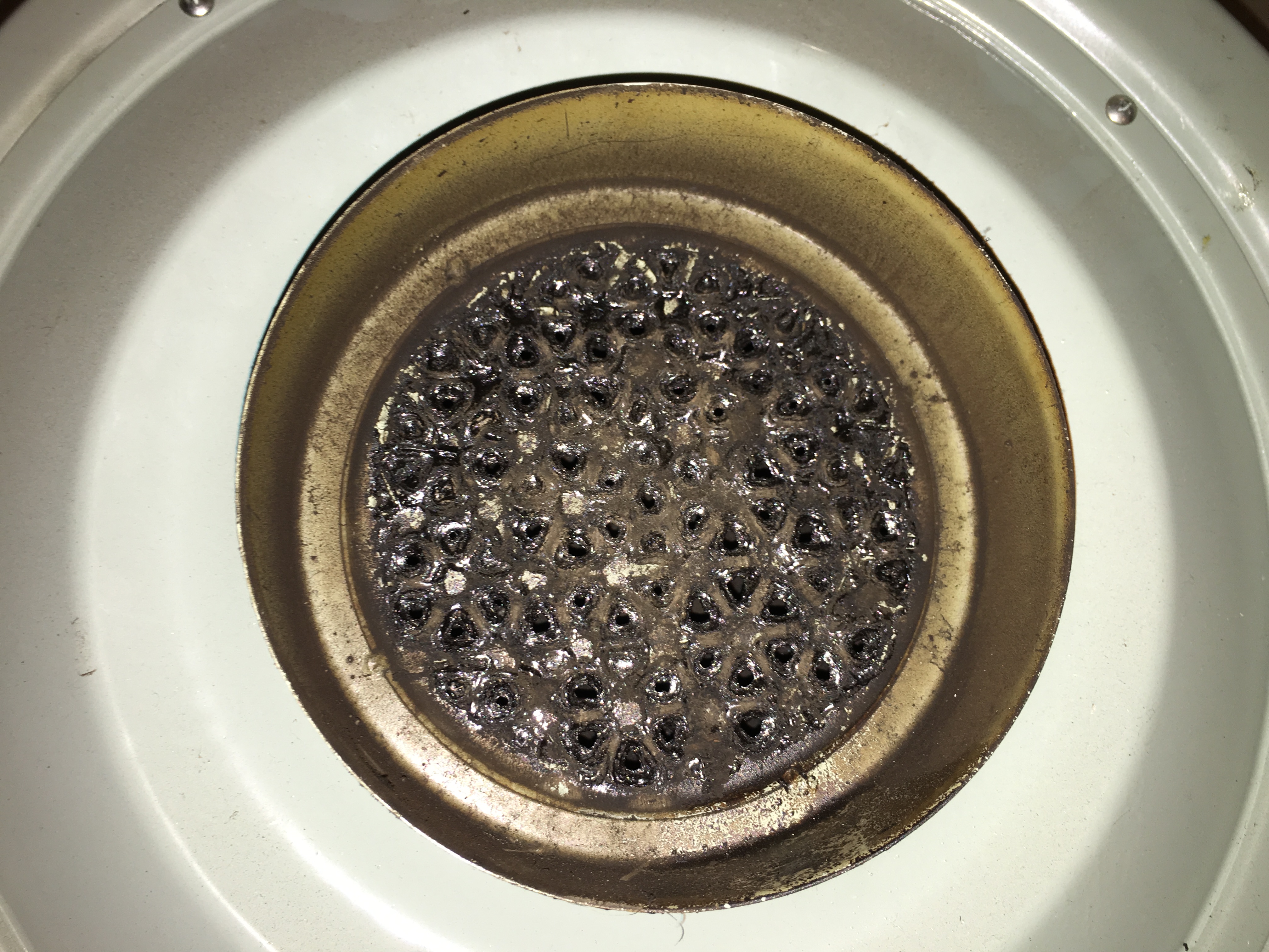
What can happen if we don’t understand this? The temptation is strong to just twiddle the thumbscrews on M3 until the beam comes out of the nozzle. That works, to some extent. The beam may be off center on the lens, but we can compensate by tilting the beam above the lens so that the beam below the lens does pass through the nozzle. The resulting beam will strike the work at an angle. This won’t make much difference for engraving, but when we cut thicker material we will start to notice that the cut edges are at an angle. This is easy to miss at first, because the hourglass shape of the beam as it comes into and goes out of focus already cuts at a slight angle, unavoidably. As the machine drifts out of alignment, and compensating adjustments are made at M3, the angle gets worse, until the beam reaches the edge of the lens. At that point it starts to burn the rubber gasket, which damages the lens and generates a plume of debris that contaminates M3. Which is exactly what happened on our laser in August. I finally got this all figured out and the laser properly aligned on August 20.