About Sol Diego

Sol Diego is an art collaborative, whose mission is to fortify the San Diego Regional Burning Man community through art making, by utilizing, sharing and developing the unique skills of its members while following the Ten Principles of Burning Man. Sol Diego achieves its mission by: * Annually, creating a large-scale, interactive installation to represent the San Diego region at the Burning Man festival through CORE (Circle of Regional Effigies) project or as an independent art project. * Outreaching within the San Diego Regional Burning Man community, to recruit new members and enrich our culture, through events such as YouTopia and Figment. * Developing outreach to the greater San Diego community.

Rotary Adapter Workshop

On April 12 we had a scheduled workshop session in the laser room with the goal of setting up and calibrating the two rotary adapters for use with the laser in its “new” configuration, and creating a set of simple procedures for laser users to follow in order to use one of the rotary adapters. I was joined by Kip, Guy, Renee, and Sriram, who were all very helpful in trying to figure things out.

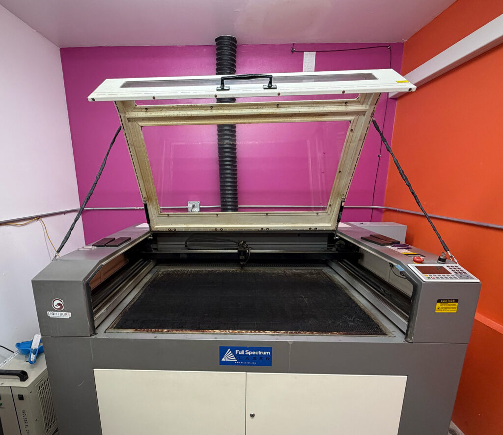
A rotary adapter replaces the Y-axis motion of the gantry with rotary motion of the work piece, enabling the laser to work on a cylindrical or conical object. This has always meant unplugging the gantry and plugging in the rotary adapter in the same place. That’s what the original laser controller expected, and it worked fine. Enabling the rotary adapter with the old software just meant a different setting for calibrating the Y axis.

As best we could figure out at the workshop, this doesn’t work as expected with the new controller. If we enable the rotary adapter, the job can’t be started by pressing the Start button, as is our standard procedure. If we instead used the Send button and then started the job from the laser’s control panel, the job would try to run, but there would be no motion on the rotary axis. This despite the fact that jogging the position manually in the Y axis did correctly cause the rotary adapter to spin. We only figured out that much by reading forum posts online.

We were able to get a rotary job to run with both axes, but only by turning off the switch in Lightburn that enables the rotary adapter. So, as far as Lightburn and the Ruida controller were concerned, it was just running a normal flat job on the bed. Of course, the Y axis calibration was used instead of any rotary axis calibration. If we wanted to use this as the standard procedure for rotary jobs, we’d have to ask the user to change the calibration setting, and then remember to change it back after the rotary job is completed. This seems inconvenient and error-prone, and risks exposing a beginner laser user to extra complexity needed only by users of the rotary adapter. This would probably be unacceptable, especially given that we’ve gotten by this long without the rotary adapters being commonly used.

Our best guess is that we need to connect the rotary adapter to the Ruida controller’s “U” axis, which is currently unconnected. In order to do that, we’ll need to install a fourth stepper motor controller (in addition to the existing X, Y, and Z axis controllers). I have that stepper motor controller on order.

It’s also possible that there are controller settings and/or Lightburn software settings that need to be adjusted in order to make it work with the old method (unplugging the gantry and plugging the rotary adapter into the Y axis controller). If so, I’d think we would have learned about those settings from the forum threads we read, but we did not.

The five of us will get together for a followup workshop once the new controller has arrived.

Progress on Camera Installation

Work is underway to add a camera to our laser. The camera will be installed on the underside of the laser’s lid, looking down onto the bed. After you’ve placed your material on the work bed of the laser, you’ll click the camera icon. This will take a snapshot of the bed with the material placed, and make that snapshot the background in the drawing area of the Lightburn software. It will then be easy to draw your design right on the image of your material, without having to fiddle around with aligning your material with your drawing. This has proven to be a nice convenience on newer model lasers that come equipped with a camera, so we can expect it to be helpful when added to our laser, which is now almost twelve years old.

For this to work well, the camera has to be in the exact same 3-dimensional position every time it’s used as when it was installed and calibrated. Our laser’s lid wasn’t originally designed with this requirement in mind, so I’ve made some modifications. Our laser already has an upgraded hinge, because the original hinges kept breaking. I replaced the four tiny cast aluminum (!) hinges with a beefy steel piano hinge running the full width of the lid. This hinge has very little mechanical play, so the camera’s X axis is well defined, as is the distance from the hinge pin to the camera. That just leaves the angle of tilt of the lid when it’s open.

The lid has pneumatic lifters, one on each side. These make it much easier to lift the heavy lid, and they keep the lid up after you’ve lifted it. However, the lifters get tired over months and years of use, and the open angle of the lid begins to droop. My idea for coping with this problem is to add cables, one on each side of the lid, that constrain exactly how high the lid can be opened. The pneumatic lifters will push against the cables to reach the same maximum height every time.

The cables are made out of eighth-inch stainless steel wire rope, with standard hardware, including a turnbuckle to allow each cable to be adjusted in length. Because the wire rope has sharp ends in multiple places, I’ve encased the wire rope and most of its hardware in a protective plastic sheath. A carabiner at each cable end then clips to a screw eye installed in the lid or chassis. Here’s what that looks like today:

Camera installation and calibration will be the next step.

February Class Scheduled

Basic laser operation and safety class is scheduled for Tuesday, February 24, at 6:30pm – 10pm.

Please email me class@colaser.org to reserve your place in the class. Because the laser room is small, the class size is limited to 6.

Expect about 90 minutes in the classroom, followed by practical hands-on exercises in the laser room. Once you complete the class, you’ll be able to schedule time on the laser to do your own projects.

Engraving Steel

I’ve been saying that the laser can’t engrave metals, with the possible exception of light engraving on stainless steel. Well, after class this afternoon we decided to try it. Turns out, the laser really can engrave stainless steel, for at least this one (unknown) type of stainless. It cuts a nice little divot out of the steel. The skull logo is about one inch across:

IMG_4355

Emboldened by this result, we also tried engraving one of the steel weights. These are standard cold-rolled steel, not stainless. They aren’t rusting because I sprayed them with clear spray paint. The laser successfully marked the surface of the steel, but didn’t penetrate to any significant depth. (Or maybe it just burned the clear spray paint. I didn’t have any unpainted steel handy.) The text is about two inches across.

IMG_4356

Both of these were vector jobs cut at 100% current, 100% power, and 10% speed. The speed could be lowered even more to get a deeper cut. Even these big thick chunks of metal were noticeably warm after the job.

On both jobs, you can clearly see the spot where the laser started to cut each vector. There’s less discoloration and a bit more depth in that spot. The rest of the cut is pretty consistent, but somewhat rough. You’d have to test your specific material and decide if you like the effect.