Once again today I had to replace the lens and mirror 3 in the laser today. Thanks to Paul M for letting me know about the problem.
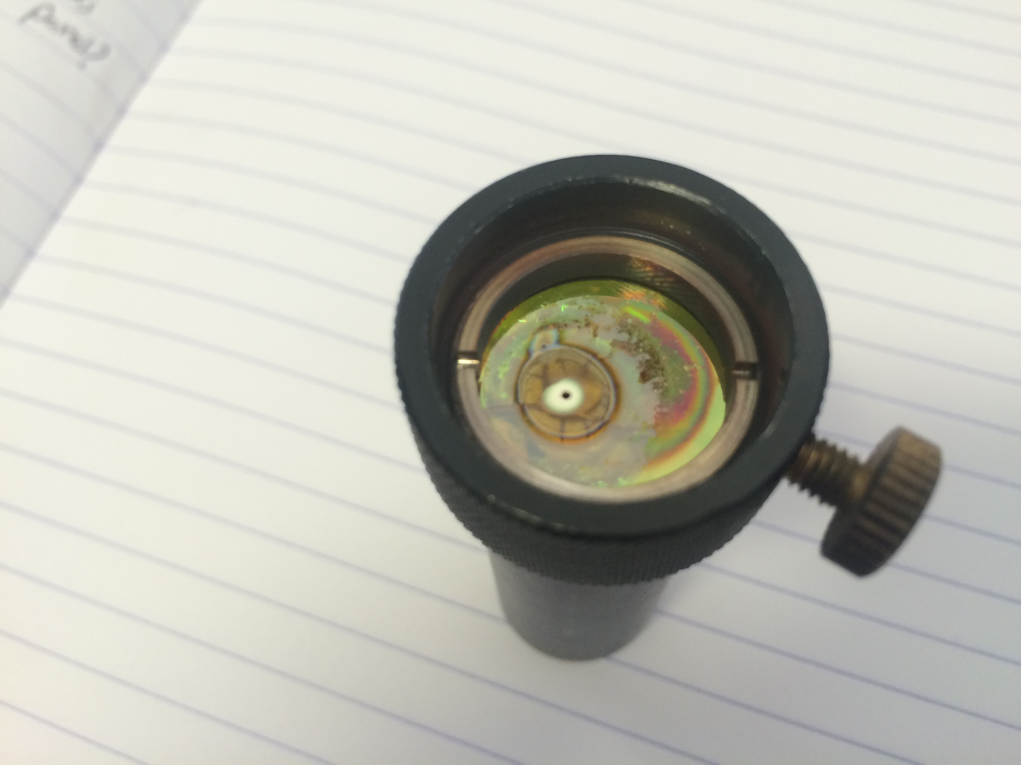
Lens destroyed
Once again today I had to replace the lens and mirror 3 in the laser today. Thanks to Paul M for letting me know about the problem.
Lens destroyed
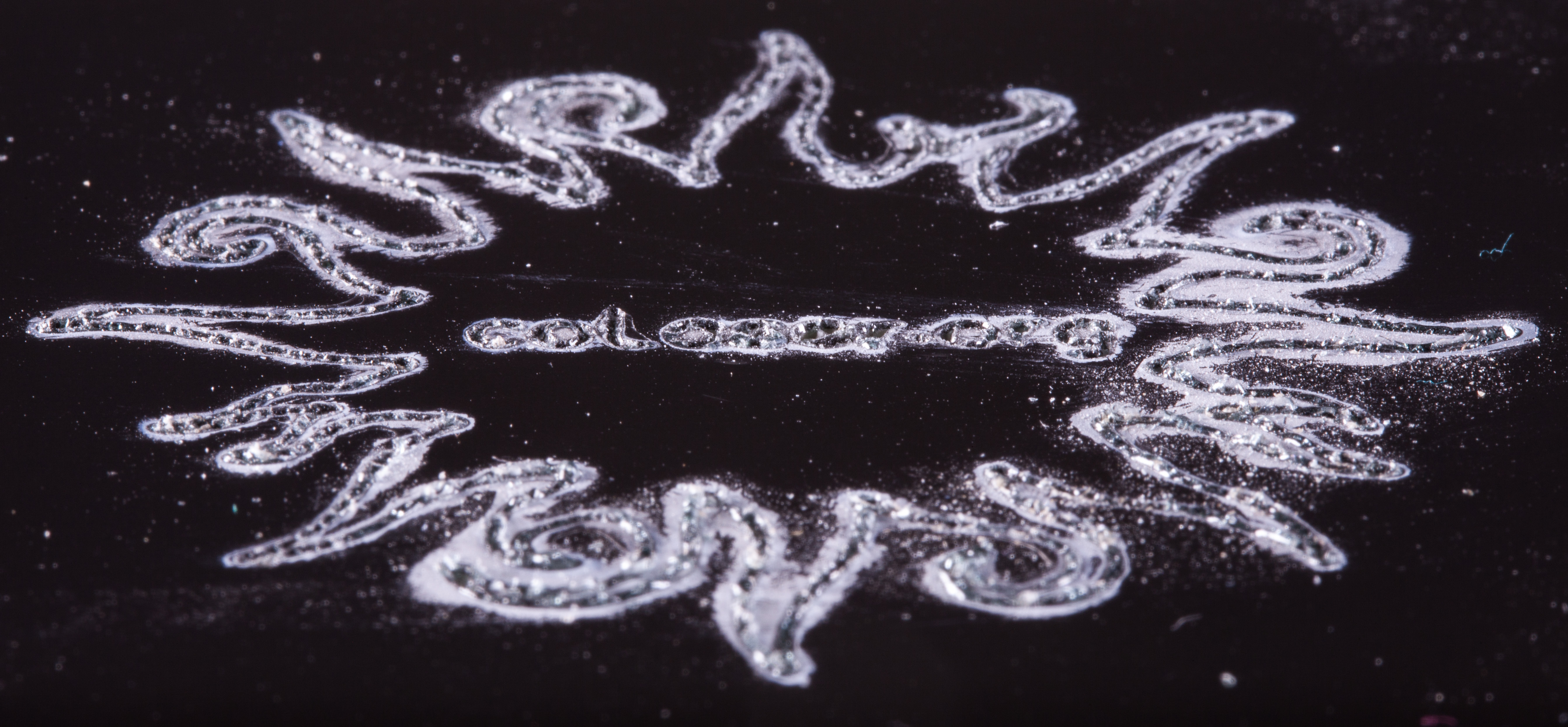
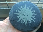
At a recent class, Sonie had the idea to search the web for henna patterns. We found lots of great art that’s perfect for raster engraving on the laser.
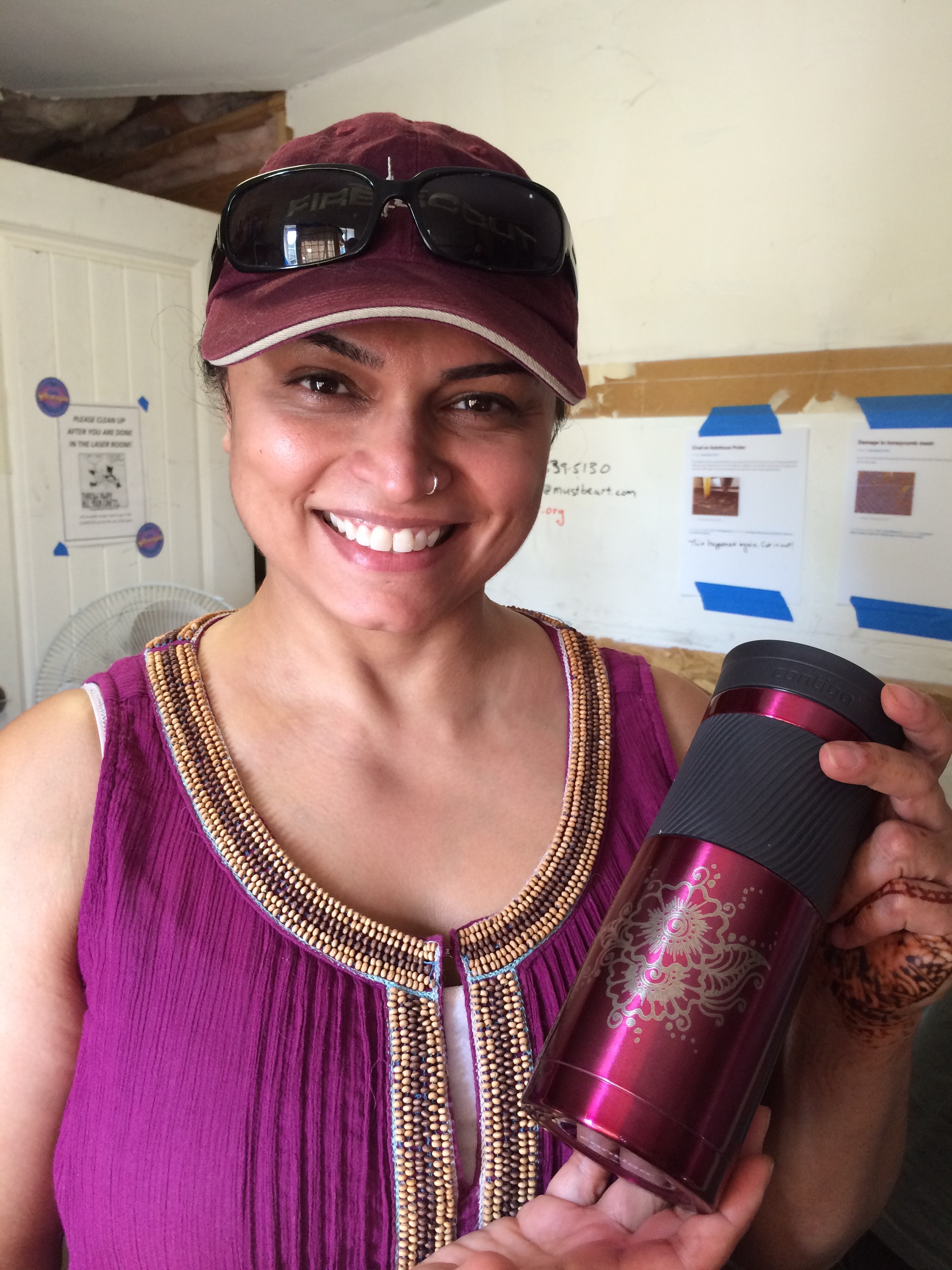
Sonie showing off her anodized aluminum water bottle with the henna pattern freshly engraved on the rotary adapter.
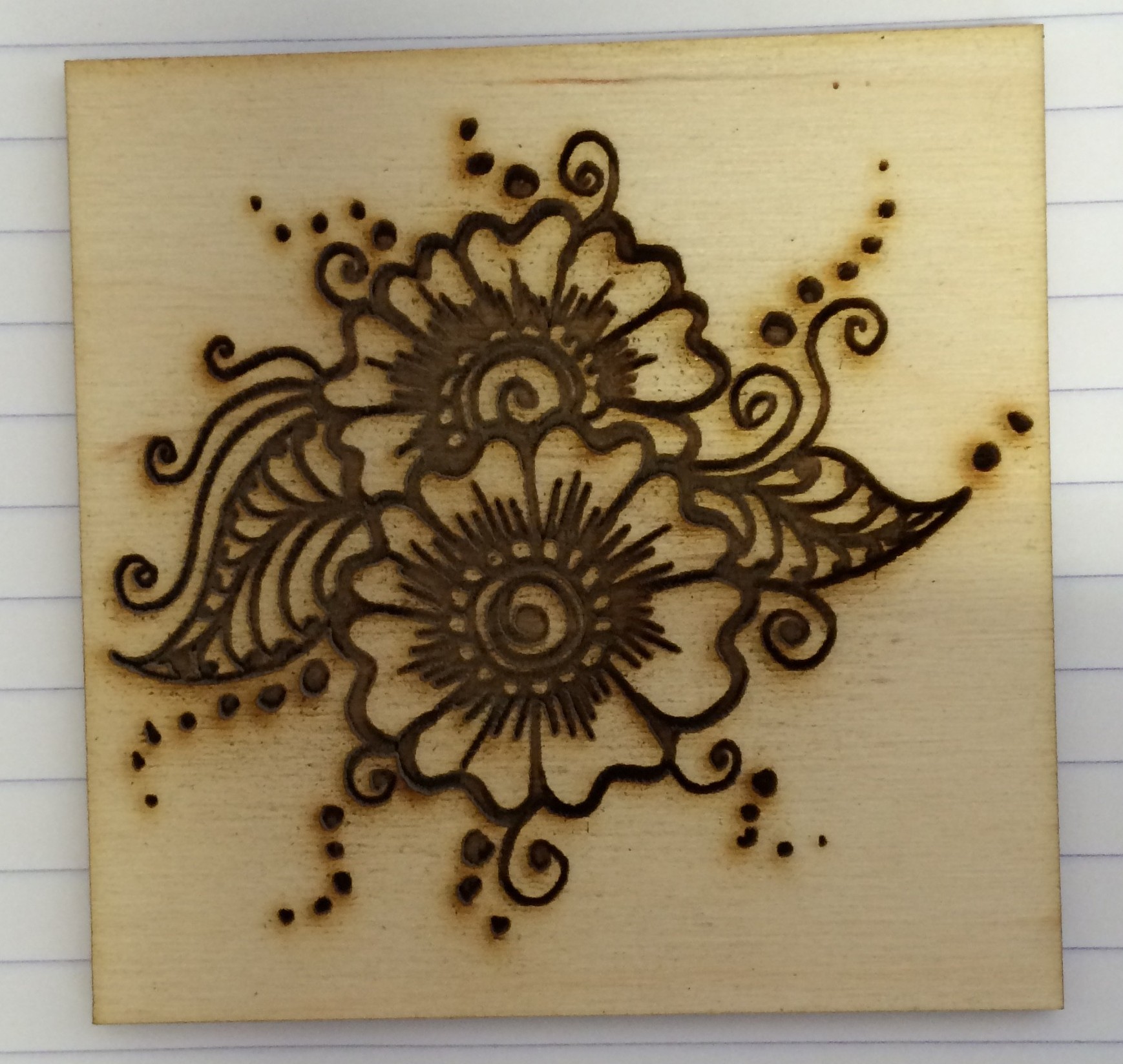
Henna pattern engraved on plywood
The last set of classes filled up and more, so I’ve scheduled two more dates for laser training classes:
Saturday afternoon, June 6, at 1pm
Monday evening, June 8, at 6pm.
Same deal as last time. Email class@colaser.org to sign up.
Basic laser operation and safety classes are scheduled for Sunday afternoon, May 31, at 1pm and Monday evening, June 1, at 6pm.
Please email me class@colaser.org to reserve your place in either session of the class. Because the laser room is small, the class size is limited to 6. Let me know which class you’d prefer and whether you could attend the other class if your preferred class is already full.
Expect about 90 minutes in the classroom, followed by practical hands-on exercises in the laser room. Once you complete the class, you’ll be able to schedule time on the laser to do your own projects.
I found some very inexpensive 3″×6″ ceramic tiles at Home Depot. These. They have a nice glossy black finish and they only cost 26 cents each. I decided to try to engrave them. I was hoping to be able to blast cleanly through the black glaze and reveal the bright white ceramic underneath. It didn’t exactly work out that way.
Here are pictures of my results. The upper left tile is blank. The one below it has been vector engraved at two different power levels. The three on the right have been raster engraved at varying speeds and powers.
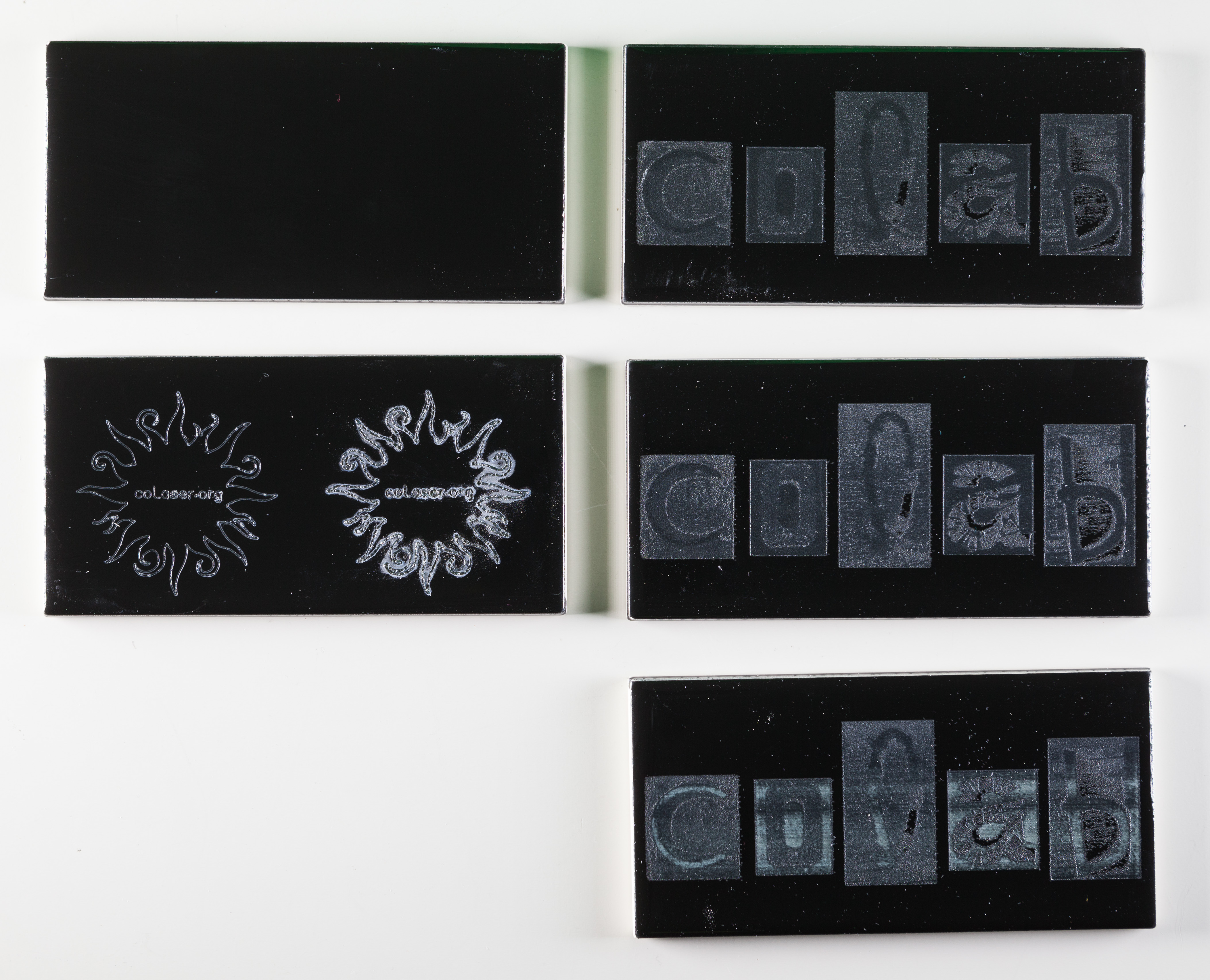
The raster engraving never did reveal any clean tile. The bluish tint I believe came from the blue paper towel I used to wipe away the ceramic dust after engraving.
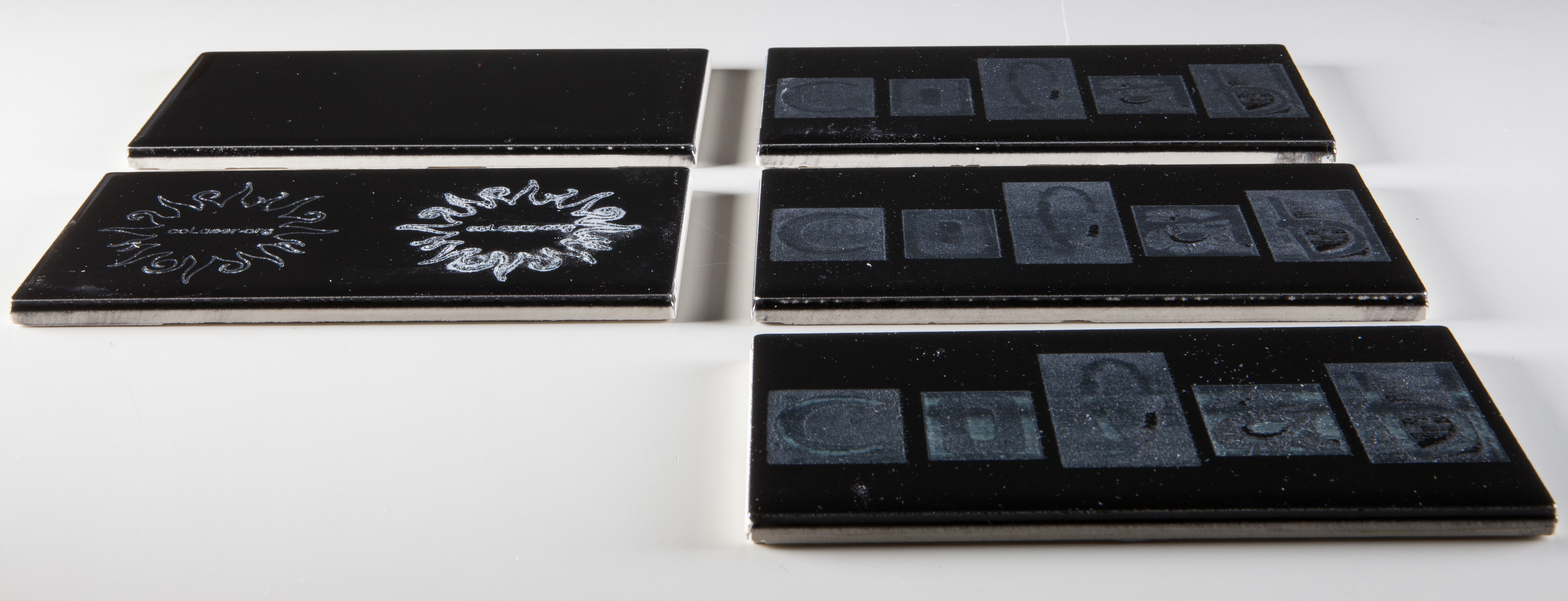
Below is a close-up view of the lower power vector effort. It’s pretty clean, but the line is wide and not very deep. The lighting for this photograph makes it look brighter than it really is. 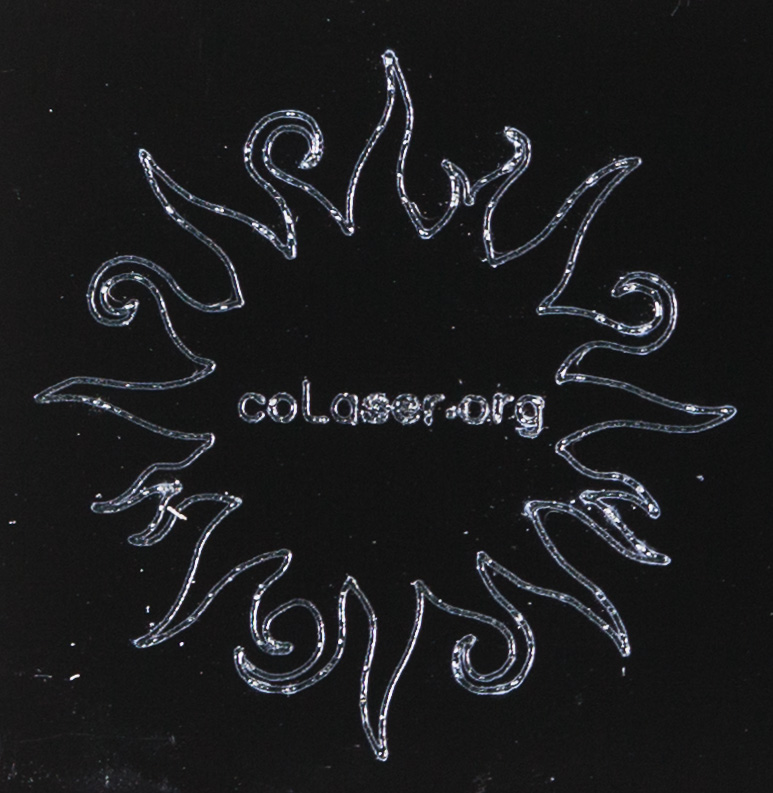
Here’s an angled close-up of the higher power vector attempt.
The material bubbled up and created a mess above the plane of the glaze. Here I’ve made some attempt to scrape it away, but the result is still not clean at all.
You can buy tiles that are designed to be laser engraved. These cheap tiles from the hardware store are no substitute.
Basic laser operation and safety class is scheduled for Tuesday, February 24, at 6:30pm – 10pm.
Please email me class@colaser.org to reserve your place in the class. Because the laser room is small, the class size is limited to 6.
Expect about 90 minutes in the classroom, followed by practical hands-on exercises in the laser room. Once you complete the class, you’ll be able to schedule time on the laser to do your own projects.
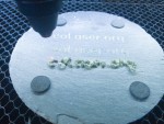
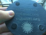
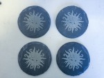
I found some slate coasters on the bargain shelf at Jo-Ann the other day, and tried laser engraving them. The results were pretty good! See the photo gallery below.
I first tried vector engraving some text. This worked nicely. The engraved line was wider than we usually see on wood or acrylic, but that just made the letters more legible. Full power and full speed seemed to work as well as anything. Slowing it down just made the letters look a little sloppier, without making them much deeper. It also noticeably warmed up the whole coaster.
My first raster engraving test was again at full power and full speed, at the lowest resolution (252 dpi). It successfully changed the color of the surface, except for a few tiny spots that were still black. It didn’t create any relief I could feel, though, just a subtle texture change. Turning the speed way down did create lots of relief, and I ended up choosing a setting midway between those two for a moderate amount of relief. Fine interior details were squeezed out by the greater effective line width; that could have been compensated for in the artwork.
This material reacts to the laser in ways I haven’t seen before. When hit with vectors, some of the material seems to melt and form thin glass-like bubbles above the surface. They easily wipe away with a paper towel, exposing the carved letters. When hit with the raster, though, the excess material appears in the form of very fine white dust. Much of the dust is deposited on the surface. Because of the ventilation air flow, all the dust ends up toward the rear of the engraving. The dust is easily wiped off. I didn’t see any evidence of the dust getting into the laser’s optics.
Whether vector or raster engraved, the lasered areas are lighter in color than the rest of the surface. I don’t know exactly why. The black surface removed by the laser might be the result of natural aging, or it might be a factory-applied treatment. It might also have something to do with the rougher texture of the lasered surfaces. It will be interesting to see what color the engraved areas are after some time passes.
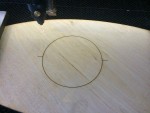
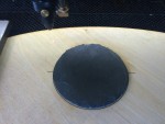
Since the laser always starts every job at the upper left corner of the rectangle that encloses the art, it’s not so easy to precisely place the laser head in the right place relative to the round coaster. To solve this problem, I created a simple jig. In CorelDraw, I added a vector circle around the outside of the raster artwork I wanted to engrave. I placed a piece of scrap material into the laser and engraved just the circle guideline on it. Then, without moving the laser head, I placed the coaster on top of the scrap and (after refocusing) centered it in the circle. I could then run the raster job and be sure the artwork would be lined up on the coaster just as I intended.
In fairly short order I was able to make a set of four coasters. With the simple jig the engraving is consistently centered so they look good even side-by-side.


After a long development cycle, the developers of the excellent free vector drawing program Inkscape have just released a major new version, numbered 0.91. There is a good article about the updates available from Libre Graphics World and you can download the new software (Windows, Mac, or Linux) from Inkscape.org.
I’ve installed the new Inkscape on the computer attached to the laser. Just in case you should have trouble with the new version, the old version (0.48.4) is also still available.
I’ve placed a HEPA air filter and cleaner in the laser room, in the hope that it will reduce the general stench of burned material and also cut down on the ambient dust level. It’s not in any way a substitute for the laser’s exhaust blower, which vents almost all the smoke to the outside. The HEPA filter is just for our comfort when we’re in the laser room.
The HEPA filter has a timer built in. I suggest you set it to run for 8 hours (the longest timer setting) when you leave the room, if you’ve made any smoke during that session. We’ll see how well that works.
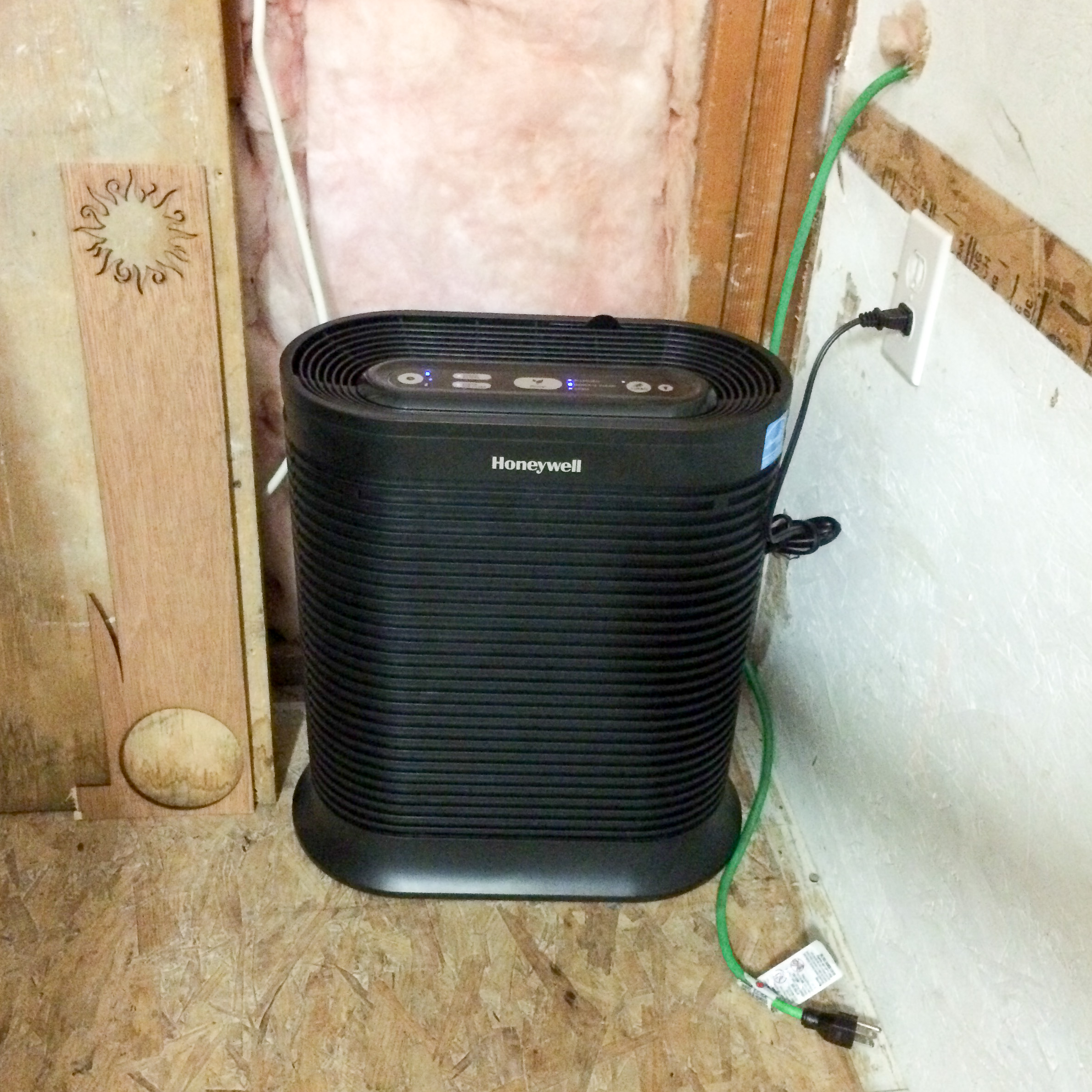
HEPA Air Cleaner
Basic laser operation and safety class is scheduled for Sunday, January 11th at 1pm, and for Sunday, January 18th at 1pm.
Please email me class@colaser.org to reserve your place in either class. Because the laser room is small, the class size is limited to 6.
Expect about 90 minutes in the classroom, followed by practical hands-on exercises in the laser room. Once you complete the class, you’ll be able to schedule time on the laser to do your own projects.