After completing the recent blog post about Combining Raster and Vector data, my next step was to add the same information to the Keynote presentation I use when teaching the basic operation and safety class. In doing so, I came up with a way to show how RetinaEngrave3D renders raster and vector data for different kinds of input.
Start by examining this screen capture from CorelDraw of our test subjects.
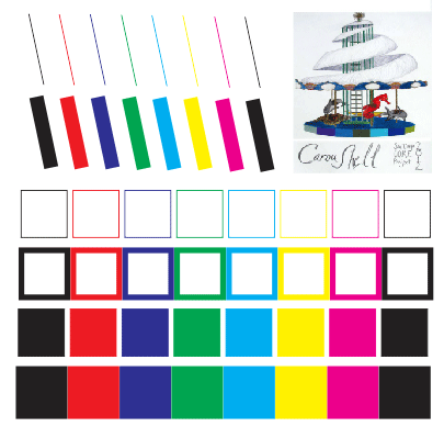
In the upper left, we have eight lines drawn with the width set to “hairline”, which is CorelDraw’s way of saying that the lines have no width, they’re just lines. The lines are in all the primary colors recognized by RE3D: black, red, blue, green, cyan, yellow, and magenta, plus another black one. Below that, we have the same eight lines with the width set to 10 points. Below that we have four rows of colored squares. The first row is “hairline”, the second row has a few points of width. The third and fourth rows are the same as the first and second, but with a fill color as well as an outline color. Finally, in the upper right corner we have a bitmap image (a color scan of the original concept drawing for the Caroushell C.O.R.E. 2012 project).
Now, suppose we “print” this to RetinaEngrave3D. The laser software interprets the data it gets from the drawing software twice, once for raster and once for vector.
Vector Rendering
Here’s the result on the Vector Cut tab:
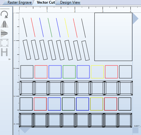
As you can see, RE3D has preserved the colors on all the “hairline” vectors, but every vector that has a width has been slammed to black. What’s more, only the “hairline” lines are still the vectors as we drew them. All the wide lines have been rendered as outlines of the area they cover. If you look closely at the squares drawn with wide lines, you can see that each side of the square has been separately outlined, with messy overlap in the corners. Even more interesting, the filled squares with wide lines have three outlines: one for each side of the wide line, and one for the filled interior.
This is unlikely to be what you want, so you’ll probably want to make sure everything you draw as a vector is drawn with the “hairline” width. Notice that if you draw a line with a small width (say, 1 point), you’ll end up with something on the vector tab that looks like a plain line, but is actually a very skinny box. Even if the width is negligible, the laser will trace the line twice. This slows down your job, and may make those lines visibly wider or darker colored.
RE3D has made no attempt to turn the bitmap image data into vectors, but it does capture the edges of it as a black vector rectangle, even though there was no line drawn around the image in CorelDraw.
RE3D gives you separate power and speed controls for each color, including black, but as you can see it creates extra black vectors whenever it sees drawing features that have width. For this reason, you will probably need to avoid drawing in black whenever your drawing isn’t entirely made of “hairline” vectors. If you do, you’ll know that anything that appears in black on the vector tab is a mistake.
Raster Rendering
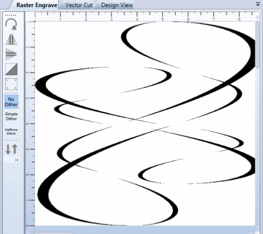
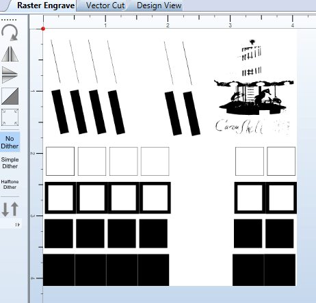
Here’s what it looks like on the Raster Engrave tab:
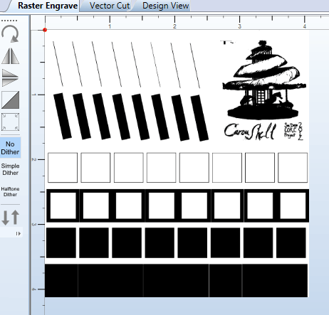
On the raster tab, everything is black, and RE3D has tried hard to capture everything you drew as some kind of raster image. Even the “hairline” lines and squares have resulted in raster data being generated. If you intended these features to be vector only, that’s a problem.
There’s no rectangle around the bitmap image here, but every area in the image that wasn’t very close to white is now shown as black. In this case, it’s a pretty good rendering of the image, so that might be perfectly fine. If your original image had more dark colors in it, this result might be pretty ugly.
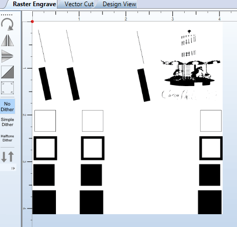
The solution in both cases is to adjust the B/W Threshold slider. In the image above, the threshold is set to 235, which is pretty close to the top of the range (255). If we lower the threshold, more and more of the lighter colored features will disappear from the raster preview. Here’s threshold 216:
Now the yellow features, and the lightest parts of the image, have dropped out.
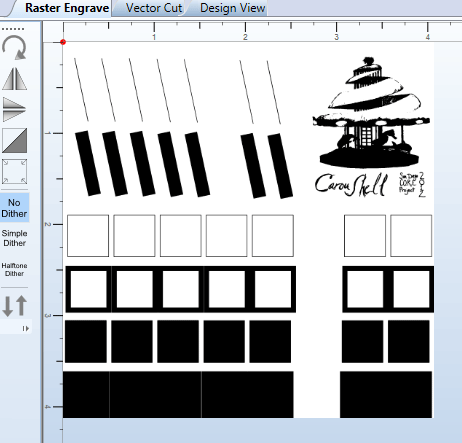
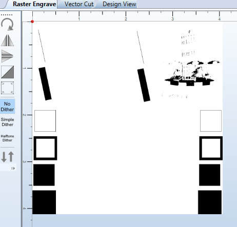
Here’s threshold 130:
Now the cyan features have also dropped out, and the image data is starting to get pretty skeletal.
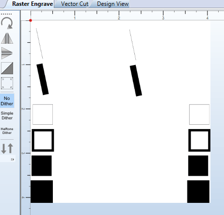
Here’s threshold 105:
Now we’ve eliminated the red, green, and magenta features. The image is lighter still, but now it’s starting to show some interesting details in the lower platform area.
Here’s threshold 72:
All the non-black features are gone, and there isn’t much left of the bitmap either.
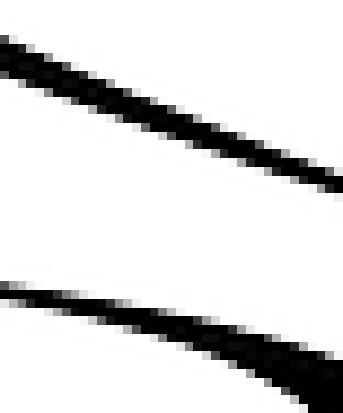
Here’s threshold 7:
Now everything that isn’t really black is gone. Apparently the bitmap image didn’t contain any truly black pixels.
So, the B/W Threshold slider lets you get rid of the raster data that was generated from vector input, and it also lets you adjust the rendering of the bitmap image into black and white. If you can find a setting that does both with great results, then that’s all you need to do.
When the B/W Threshold Setting Is Not Enough
But what if the threshold setting you need to make the bitmap image look its best doesn’t eliminate all the vector features?
In some cases, you can just change the colors used for vector features to lighter colors. If you can make all your vectors yellow, then cyan, and so on, then you might not need to work any harder. But what if you need lots of different colors, in order to use different power and speed settings for different features of your drawing? In that case you might well run out of light-enough colors.
For that case, RE3D provides a checkbox in the Import Options section, called “Ignore Thin Vectors”. If this box is checked when you “print” your job to RE3D, the “hairline” vectors won’t appear on the raster tab at all. (There is also a “Tolerance” setting which is supposed to control how wide a line can be and still be ignored, but it doesn’t appear to do anything.)
What’s more, if you check the “Ignore Thin Vectors” box, the lines with non-hairline width won’t appear on the vector tab either! That means those features won’t appear anywhere in your job, which can be confusing. If you accidentally have smaller features drawn with non-hairline width, it would be very easy not to notice the missing features until it’s too late. So, use the “Ignore Thin Vectors” option with caution.
There’s also an “Ignore All Vector” checkbox, but it doesn’t do anything useful for us. It still doesn’t ignore the wide (non-“hairline”) vectors, and it wipes all your vectors off of the vector tab. The only reason this might be useful is if your file contains so many detailed vectors that it takes a long time to import, and you don’t want them.
You may run across cases where there is no combination of RE3D settings that works the way you want. For example, if you have multiple bitmap images, and they don’t all look good at the same B/W Threshold setting. For that case, the simplest solution is probably to pre-render the bitmap images in your drawing program before “printing” the job to RE3D. CorelDraw has many features under the Bitmaps menu for this kind of work.
Sometimes it might be easier to run the vector and raster parts of your job separately. See the Combining Raster and Vector post, near the bottom, for tips on how to do that.