Happy anniversary to Colaser! It cuts its first job three years ago today.
Colaser Turns 3
Reply

Happy anniversary to Colaser! It cuts its first job three years ago today.
Two new sessions of the basic operation and safety training course for the Sol Diego laser cutter/engraver at Colab have been scheduled for THIS WEEKEND:
Saturday, August 5, 1pm to 5pm (now ALMOST FULL)
OR
Sunday, August 6, 1pm to 5pm. (now FULL)
If you’d like to sign up for one of these classes, please email class@colaser.org ASAP and let me know which session you’d prefer. The laser room is small, so class size is limited.
If you NEED TO USE THE LASER BEFORE BURNING MAN, please say so in your email. If you are willing to give up your spot in the class for somebody who does need to get trained before the burn, please let me know that, too.
The class is free, and once you’ve completed the class you’ll be able to schedule time to use the Colaser, which is also free for art and personal projects. You don’t need to bring anything special to class. Be prepared for about 90 minutes of classroom instruction, followed by hands-on exercises with the laser.
On June 23, I had to remove the beam combiner that routes the red dot spotting laser through the same optics as the cutting laser, because the cumulative damage had pretty much destroyed it. Until the beam combiner is replaced, there will be no red dot to help you see where the laser will hit your material. I have ordered a new beam combiner, and a spare.
Update (August 4): In order to get a reasonable price on this specialized optical beam combiner, I ordered direct from a supplier in China. They quote a usual shipping time of 12-20 days. It has now been 41 days. Overdue, but I can’t open a dispute until 60 days have passed. If the slow boat doesn’t eventually arrive, I’ll have to re-order.
Until then, I hope you’re not having too much trouble using the laser without the red dot.
Yesterday there was apparently a power surge on the AC power at Colab. This blew out the surge suppressors inside the high voltage power supply in the laser, with the result that the laser would not fire. This is the same failure we experienced about a year ago, so I already knew what to do and had the (inexpensive) replacement parts on hand, so the laser is already back up and running.
Two Three new sessions of the basic operation and safety training course for the Sol Diego laser cutter/engraver at Colab have been scheduled:
Tuesday, January 31, 6pm to 10pm (update: NOW FULL)
OR
Sunday, February 5, 1pm to 5pm (update: NOW FULL)
OR
Tuesday, February 7, 6pm to 10pm (update: NOW FULL)
If you’d like to sign up for one of these classes, please email class@colaser.org and let me know which session you’d prefer. The laser room is small, so class size is limited.
My quick and dirty repair of the power inlet module lasted about five weeks, and then burned up, as seen here: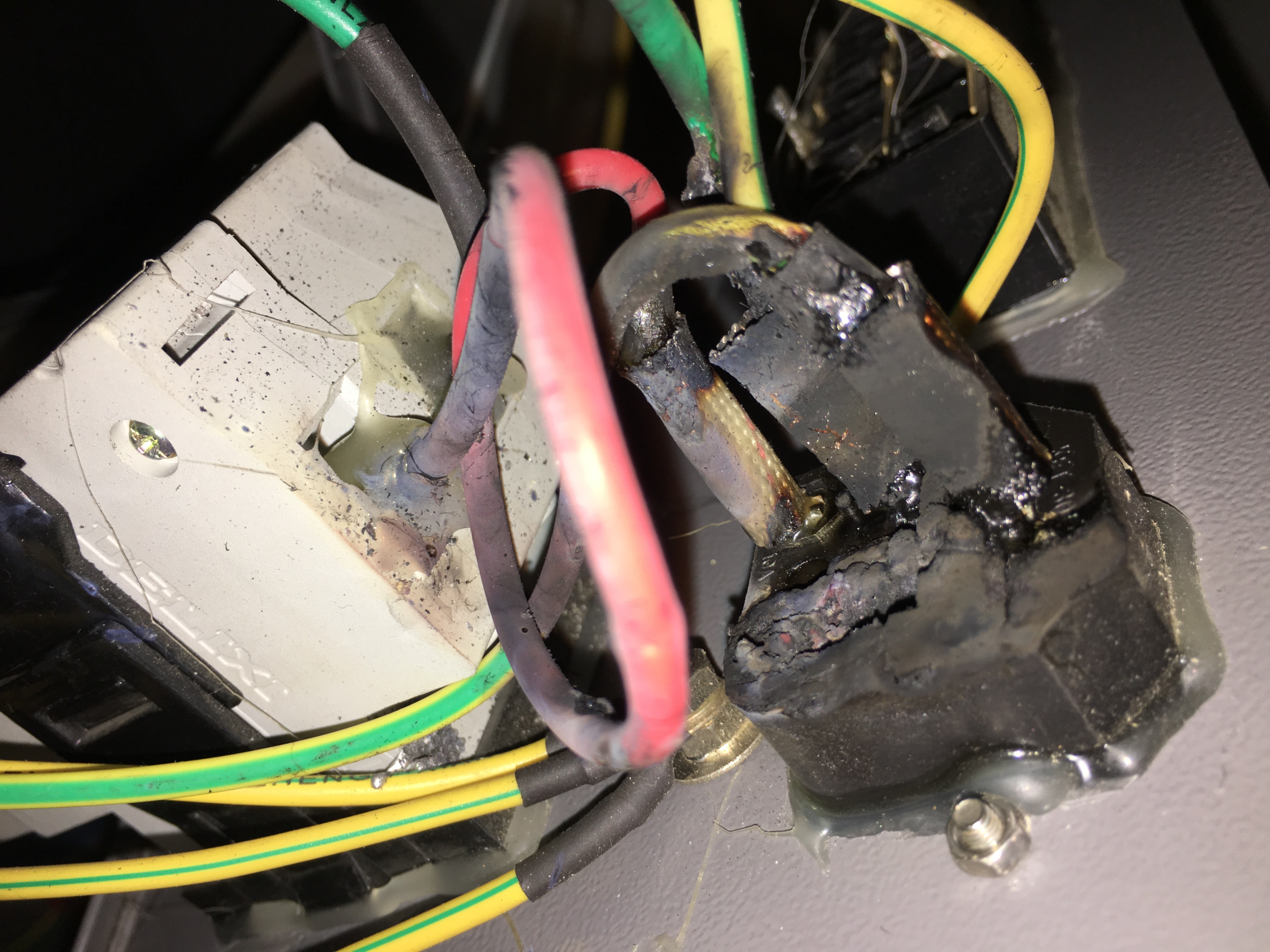
So this time I ordered and installed a replacement part (Interpower 83110131) and got a new power cord.
Instead of the excessive 20A fuses that came with the laser, I installed a 15A fuse. I plan to measure the actual current draw soon. Full Spectrum now says it should be only 5A surge and 1.5A continuous. However, when the laser was first installed it was popping a 15A circuit breaker, so I don’t believe their numbers. If I can drop down to a 10A fuse, I will, because that IEC connector is only rated for 10A.
Last night Martin reported that he was cutting some thin plywood when the laser suddenly stopped, manifesting a complete loss of power. Power at the outlet was still good, and the visible circuit breaker on the back of the machine had not tripped. It behaved, Martin suggested, as if an internal fuse or circuit breaker had blown.
Today I took a look at it, and confirmed Martin’s report. I don’t have a schematic diagram or any documentation on the electronics of the laser. The components are more or less accessible through the side doors and are mostly wired up with individual wires, so it is possible with some patience to trace the wiring. The power wiring is very carefully insulated, terminated, and glued in place, though, so it isn’t so easy to probe the circuits.
The power comes in from the wall through a standard IEC cable and matching chassis connector, like a desktop computer. Then it goes through a device labeled in Chinese that appears to be a relative of a ground fault circuit interrupter, or GFCI, like you see on outlets in wet areas, plus a circuit breaker. Then it disappears into a wiring trough, to reappear at the front panel. One wire goes through the big red E-stop switch, and the other wire goes through the key switch, and then they both go back into the wiring trough. They come out again in the side cabinet, and go through an EMI filter before being distributed to the various DC power supplies. The connections to the EMI filter are push-on tabs, so they can be backed off a bit and probed. There was no voltage there, with power connected and the switches all on.
OK, so it’s all wires and switches, except for the GFCI. Now I’ve known GFCIs to fail, so I suspected it. I just needed confirmation that power was present at the input to the GFCI, and absent at the output. Lacking any really good way to probe this, I tried poking the sharp ends of the voltmeter’s probes through the soft insulation on the wires. I saw no voltage on the input, so I suspected the probing technique was not working.
To check on the probing technique, I switched the meter to ohms and tried to look at connectivity between the IEC connector and the inputs to the GFCI. I couldn’t find any connection there, either. Maybe that just wasn’t an effective way to probe the wires.
Along about this time, I happened to take a closer look at the IEC connector and noticed that it had an integral fuse. Aha! I bet that fuse was blown. So I pulled out the fuse holder. I was impressed to see that the fuse holder also contained a spare fuse. Nice touch. But when I measured the installed fuse, it was good. In fact it measured almost exactly the same as the spare fuse.
Now I was ready to doubt every connection. I probed around everywhere, not trusting anything. And I found something unexpected. There was no connection between the hot pin on the IEC connector and the fuse. Mind you, these are all part of the same piece, since the fuse holder is integral to the IEC connector.
The photo here shows the back side of the IEC connector/fuse holder, and you can see the common chassis ground post just below it.
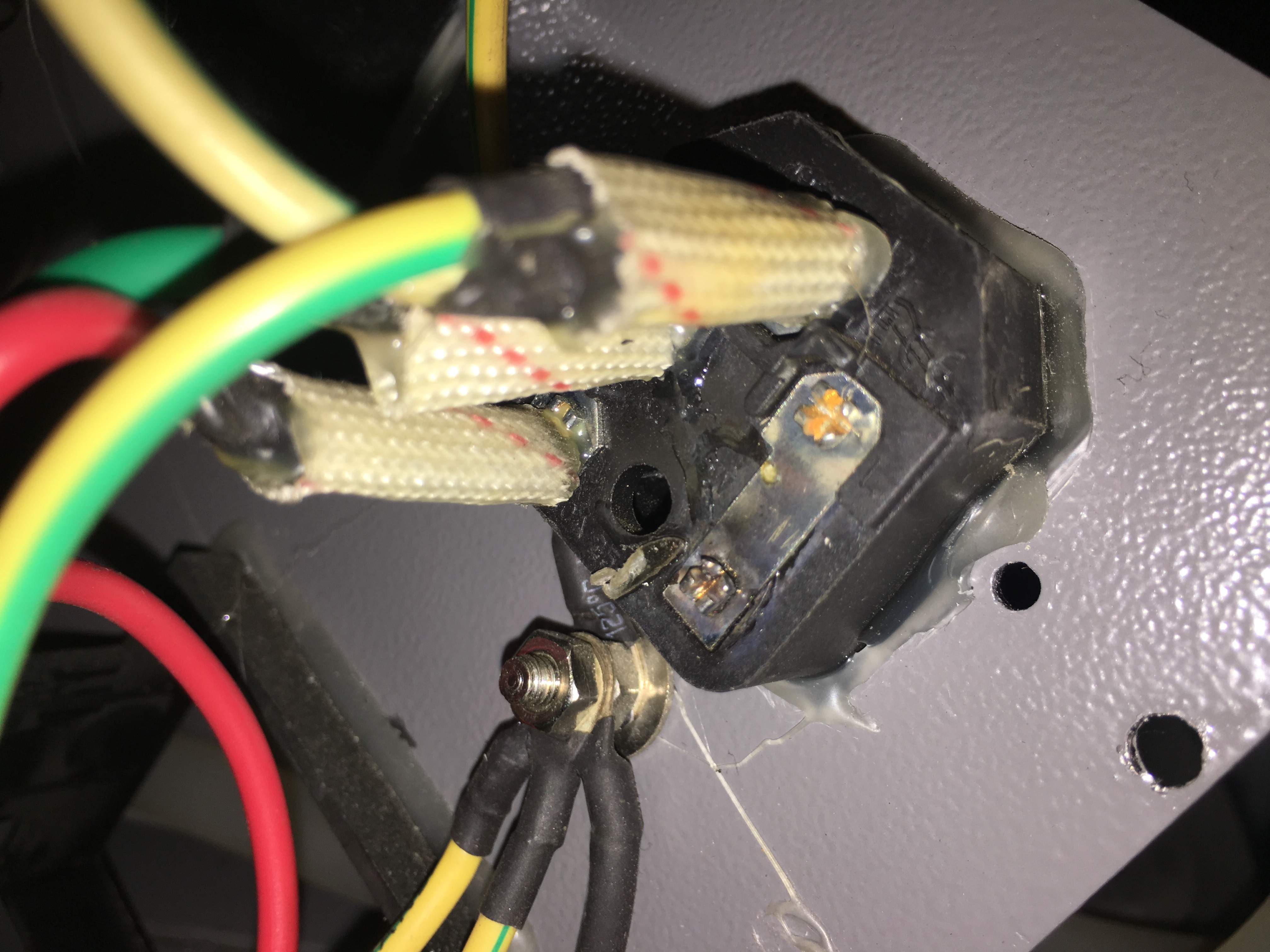
On the right side, you can see a metal strap with two studs sticking through it. The upper stud (the nice shiny golden one) is the hot pin of the IEC connector, and it makes a very solid connection to the strap. The lower stud (the blackened one) is one contact of the fuse holder. It looks connected at first glance, but it isn’t. There’s a tiny annular gap around the stud, and it doesn’t touch the strap at all. It must have touched, until yesterday evening, but it must have been marginally bad from the beginning. I suspect it got worse very slowly, until it reached a point of thermal runaway and burned out suddenly.
I didn’t think I’d be able to source a replacement connector locally on a Saturday afternoon, so instead Robert donated the purchase of a soldering gun and a wire brush from our neighbor Home Depot, and I blobbed some solder between the stud and the strap. Problem solved!
That connector would have been at the very bottom of my list of suspected components.
As a test I was cutting an array of five-pointed stars about 3/4″ in diameter out of quarter-inch acrylic. It took about 60 speed and 100 power to cut the outline of the stars all the way through the acrylic, but they remained connected to the sheet at the sharp corners. Even at 40 speed, they had to be mechanically punched out, and the points were rough. The whole area of the material was quite warm at the end of the job. I’m thinking the sharp points were rewelding to the sheet after the cut.
As an experiment I tried cutting at 80 speed, but with the number of passes in the vector settings table set to 2. That should be effectively about the same power and about the same overall duration as cutting at 40 speed. Sure enough, the results were pretty similar. The stars were still stuck in the sheet by their corners. With passes set to 2, each individual star is cut out twice before moving to the next one. There’s no delay between the two passes. For a small job like a single star, there’s not much benefit in dividing the power up into two passes.
Then I changed the passes setting back to 1, and ran the whole job twice. That’s the same effective power delivered as setting passes to 2 and running the job once, but it gives each cut time to cool down between the two doses of heat. The result was much better. The stars dropped out of the sheet (with a bit of shaking) and their points were pretty clean.
Consider using this trick if you run into rewelding on sharp corners when cutting thick acrylic.
Today I went in to try and diagnose the problem with reduced power. Well, the problem is gone, but I didn’t do anything to fix it.
My hopeful theory was that the surge suppressors inside the high voltage power supply were starting to fail again. That’d be a cheap and easy repair. I opened up the high voltage power supply and found no visible damage to the surge suppressors, and they tested good with a multimeter (now in the toolbox for future use).
The power faded out during a class session, where we were running small jobs with longish pauses in between. It was a warm day, but far from the warmest we’ve had to deal with this year. Today I tried running several longish jobs at high power to stress the system, but couldn’t get it to misbehave.
Terry ran some quarter-inch acrylic cuts last night and also got normal performance (60 speed and 100 power to cut through).
So, I don’t know what was wrong, or whether it will be wrong again anytime soon.
Toward the end of class yesterday we noted that the laser output power wasn’t up to par. Material that can usually be cut at 20% power was requiring 70%. Alignment test pulses were weaker than usual, even before passing through any optics.
That leaves the laser tube itself and the electronics. I’m hoping this is the same problem we had before, which turned out to be failing surge suppressors inside the high voltage power supply. If so, that’s a cheap and easy fix. If not, we may have an expensive repair to do.
In the meantime, as far as I know it’s OK to use the laser by just cranking up the power settings (or reducing speed). Be aware, though, that it’s likely to get worse or fail entirely.