I’ve updated the comprehensive Laser Job Checklist to match the new laser configuration and software environment. You can get a PDF copy in the Downloads section on this site.
Category Archives: Tip
Raster Engraving Trick
One of the characteristics of our laser is that when raster engraving, vertical edges tend to be emphasized. As the head travels across the image, whenever it encounters a transition from laser-off to laser-on, an extra pulse of power is generated as the laser starts firing. This extra pulse of power adds to the laser’s effect on the material at that edge. Here’s an example, taken from the front cover of the first volume of our log book.
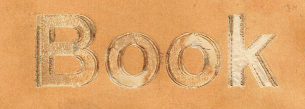
The original image artwork was filled-in black letters, with no outline features. All the outlining you see is due to the extra power pulse effect. (There’s some doubling of the lines because I bumped the notebook slightly before trying a second pass.) The effect is especially noticeable in this case, because we’re engraving on paper with a colored glossy coating, which is very easy to cut and reveals differences in cutting power. If you examine the B in that image, you can see that true horizontal edges are not emphasized, but all the edges that have a vertical component have an extra outline. It doesn’t matter whether the vertical edge is on the left or right side of the filled area, because the laser fires in both directions when rastering.
Full Spectrum Laser told me this was an unavoidable property of CO2 lasers. I have my doubts about that. I suspect that smarter controller electronics could compensate for any such tendency and reduce or eliminate the problem. I’ve seen work from other brands of laser that don’t show this effect. Be that as it may, we are stuck with the problem.
Today I was calibrating laser speed and power on some scraps of light-colored leather I picked up at Artist & Craftsman Supply. For my raster test image, I just used some plain Arial text. Here’s one of my first results.

As you can see, the horizontals are pretty much invisible. The square geometry of Arial text makes the effect very noticeable. (If you look closely you can also see some evidence that the explanation I gave above isn’t the whole story.)
My usual workaround for the problem is to use more power. Most materials change color quickly from their original color to their laser-burned color, and additional power just cuts deeper into the material. If we use enough laser power to fully change the color of non-vertical features, then the vertical features won’t be darker than the other engraved areas. They’ll just be deeper, which is not nearly as obvious to the eye. That workaround won’t work with this leather, any more than it worked with the logbook cover above, because the leather has a thin top layer that we don’t really want to penetrate.
Today’s invention is a new workaround. I rotated the image of the text by 45 degrees in the drawing program, and also rotated the leather 45 degrees on the laser bed. In effect, this rotates the raster scan 45 degrees with respect to the artwork, without otherwise changing the design. Here’s the result.

As you can see, this is like magic on the small Arial text. The dominant horizontal and vertical lines are all rendered rather nicely. As it happens, this sample doesn’t contain any significant edges at a -45 degree angle, so all the edges are emphasized equally. The sample also doesn’t contain any wide areas to be engraved, so effectively it’s all edges. If the text were larger, you’d probably see that each stroke of the letterforms had two strong edges around a weaker middle, but that’s invisible at this scale. It would still be a nicer effect than losing the horizontal lines.
There isn’t anything magic about 45 degrees, except that it theoretically balances the effect between horizontal and vertical edges. You can use whatever rotation you need in order to minimize the visual importance of lines and edges that are parallel to the raster scan. If your artwork was a geometric design with lots of lines at 45 degree angles, you’d definitely want to use some other angle.
This isn’t a complete solution, of course, but it’s a useful trick to know about when it’s applicable.
Raster-Preventing Bug in RE3D
Lately we’ve observed a strange behavior in the print driver settings for the “Full Spectrum Engineering Driver” printer created by Retina Engrave 3D. The paper size shows as “Letter” by default, but is actually set to 36×48 inches. Since the program can’t handle rasters that big, it means that rasters just don’t show up. Trying to print excessively large rasters also seems to cause other parts of the program to misbehave in random ways.
There’s probably a setting somewhere that will fix this. Until we find it, the workaround is to go into the “Advanced” settings and change the paper size to something else, and then back to the size you actually want (Letter is good if your art fits, otherwise use the smallest paper size your art will fit on). This resets the paper size setting and the driver behaves as expected.
Ebook from FSL
Full Spectrum Laser has begin a series of Ebooks about working with lasers, and the first one is definitely worth checking out:
Designing for Laser Cutting – A Technical Ebook for Creatives
(Redistributed with permission from FSL)
Cutting Acrylic in Two Passes
As a test I was cutting an array of five-pointed stars about 3/4″ in diameter out of quarter-inch acrylic. It took about 60 speed and 100 power to cut the outline of the stars all the way through the acrylic, but they remained connected to the sheet at the sharp corners. Even at 40 speed, they had to be mechanically punched out, and the points were rough. The whole area of the material was quite warm at the end of the job. I’m thinking the sharp points were rewelding to the sheet after the cut.
As an experiment I tried cutting at 80 speed, but with the number of passes in the vector settings table set to 2. That should be effectively about the same power and about the same overall duration as cutting at 40 speed. Sure enough, the results were pretty similar. The stars were still stuck in the sheet by their corners. With passes set to 2, each individual star is cut out twice before moving to the next one. There’s no delay between the two passes. For a small job like a single star, there’s not much benefit in dividing the power up into two passes.
Then I changed the passes setting back to 1, and ran the whole job twice. That’s the same effective power delivered as setting passes to 2 and running the job once, but it gives each cut time to cool down between the two doses of heat. The result was much better. The stars dropped out of the sheet (with a bit of shaking) and their points were pretty clean.
Consider using this trick if you run into rewelding on sharp corners when cutting thick acrylic.
Cermark Test
After talking about Cermark from Thermark (now Ferro) in laser classes for two years, I finally got around to trying it. I sprayed a light coat of Cermark LMM-6000 from an aerosol can onto a few small galvanized steel plates (Strong-Tie TP35 from Home Depot) I had left over from another project. After it dried, I engraved using the laser at various settings, both raster and vector, and then washed off the rest of the spray with water.
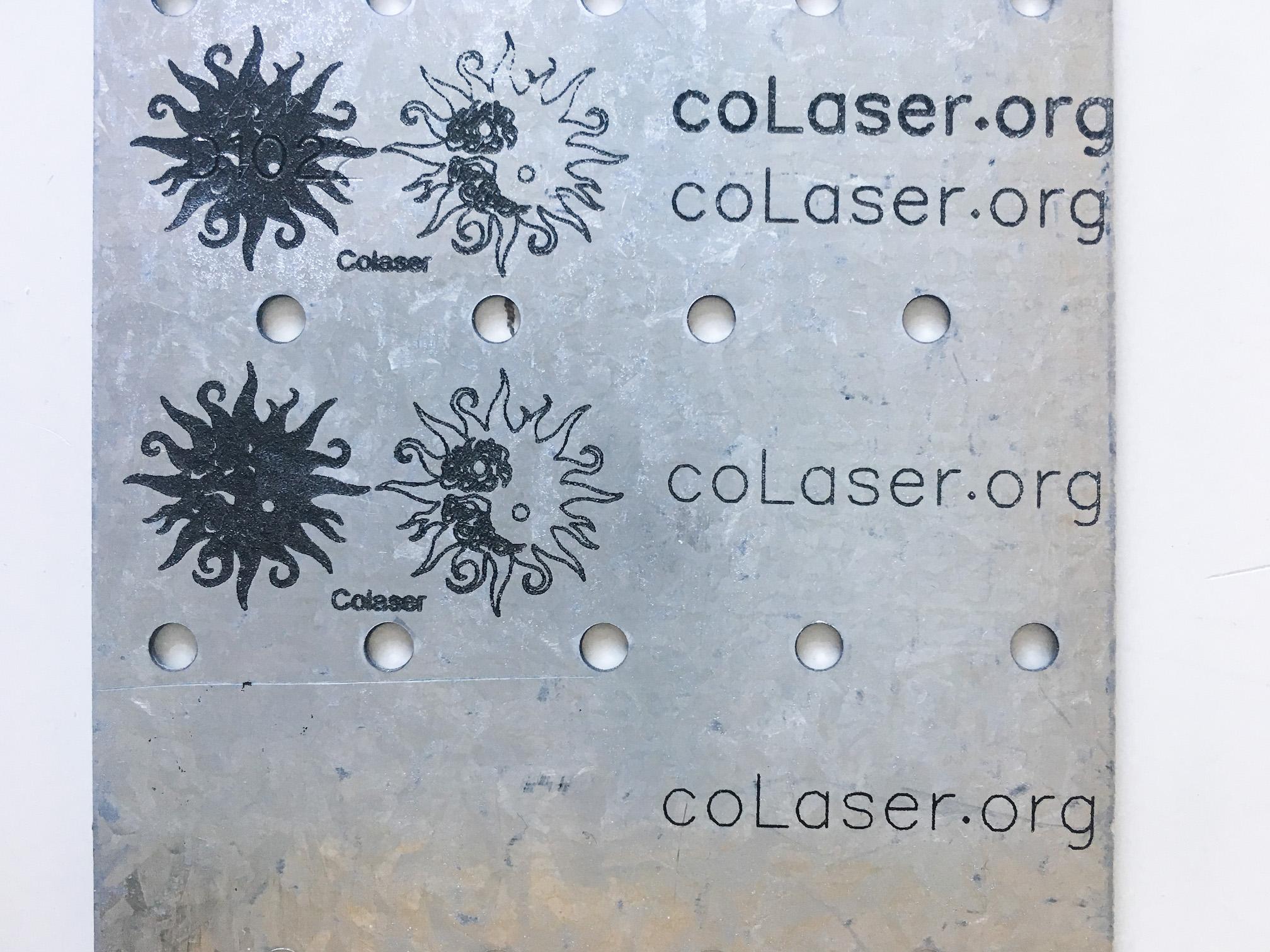
Initial test of Cermark LMM-6000 on galvanized steel plate
The sun images are about 0.75 inches in diameter; the whole plate is 3.25 inches wide. The top raster image of a filled sun, a lines-only sun, and the word “Colaser” was engraved at 100% speed and 100% power. Some of the fine detail in the cutouts is filled in, so that setting is too high. The lower raster image was engraved at 50% power, and it looks pretty good. A third raster test was done at 10% power, and it made no mark on the metal at all.
The vector test image was the text “coLaser.org”. The topmost one was done with the wrong art, so each stroke was double-cut or worse. Disregard that one. The test right below it was cut as single lines at vector settings of 100% speed and 100% power. The middle test was done at 20% power, and the bottom test was done at 5% power. All three tests look pretty good. The resulting line is just a little bit narrower at the lower power settings. Even lower power settings would be worth experimenting with.
You can see some dropouts near the top of the top sun image. I think that’s due to inadequate spray coverage. The instructions say to make a thin coating that just covers the metal. I may have been a little stingy with the spray.
The photography was a bit challenging. Depending on lighting, the mark can be nearly invisible in photos. In person, though, it looks like black on top of the metal.
The marking seems to be quite durable. It’s a bit rough to the touch, and if it were ordinary paint it would rub off easily. As a test, I tried to scrape it off with my thumbnail. That worked like a nail file: the Cermark ground down my thumbnail and took no damage. An Xacto knife was able to scrape it off. In between, scraping at it with a piece of copper was more or less a draw: some Cermark was removed, but some copper was left behind too.
There was no visible smoke or ash from the engraving, so I suppose this material is completely safe for the laser. The engraved image is visible before washing, but the appearance is not a good guide to laser power settings. The third row of raster tests looked black before washing, but did not stick to the metal. (I was in a hurry and neglected to take any photographs before washing.)
Thermark has recommended settings for this material for 30 watt and 45 watt CO2 lasers. They talk about speed in inches per second, and I don’t know offhand how that translates to the percentage speed settings we use on Retina Engrave 3D. For the 30W laser, they recommend maximum power for most materials, but on the 45W laser they suggest using lower settings for some materials. On galvanized steel, they still suggest full power at 45 watts. They don’t give any suggestions for 150W lasers like ours.
Also, note that the laser may not have been working at full power the day I ran this test. During the class later that day, the laser power was dropping significantly (for reasons yet to be determined). In any case, you’ll need to run tests with your material to determine the best settings for Cermark.
We also have a spray can of Cermark LMM-6044, which is for glass and tile. I still have yet to try that.
Learning about Alignment
It turns out there’s more to laser alignment than I thought, and more than is revealed in the written instructions or in the alignment procedure video.
 The basic alignment involves adjusting the three mirrors, shown here as M1, M2, and M3. The gantry carries M2 and M3 forward and backward along the Y axis of the machine. M3 travels left and right with the head, along the gantry in the X axis of the machine, and reflects the beam down onto the work. The infrared cutting beam comes out of the laser tube, passes unchanged through the beam combiner (BC), and bounces off M1, M2, and M3. The red laser is reflected by the beam combiner, and travels with the cutting beam as it bounces off the mirrors.
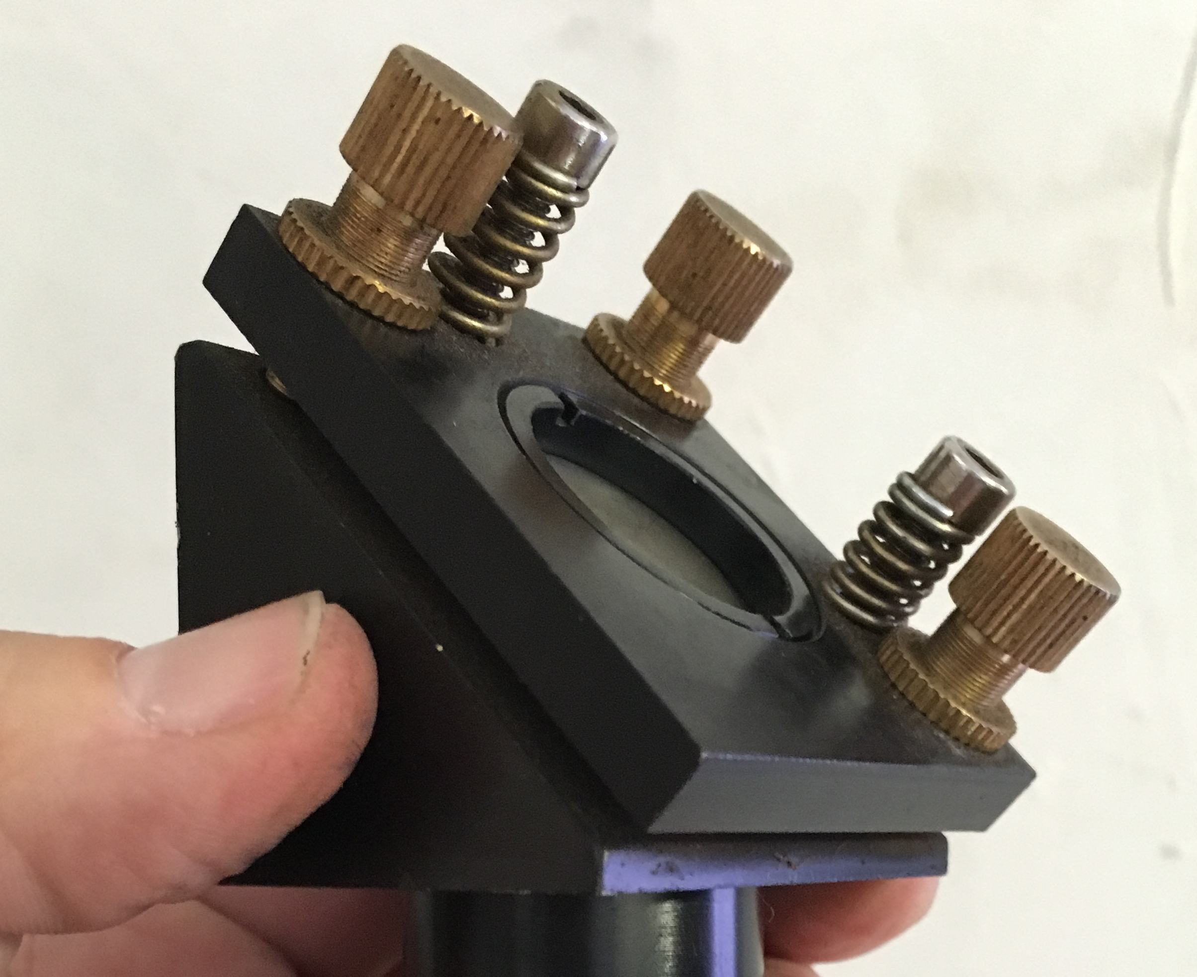 Each mirror floats in a mount like the one shown here. The three thumbscrews, pushing against the tension springs, define the position and orientation of the mirror carrier on its mount. By turning one or two of the thumbscrews, you can tilt the mirror over a pretty wide range. By turning all three, you can move the mirror a little, without changing its angle.
In the basic alignment, the first goal is to arrange for the beam to leave M3 at the same place and at the same angle, regardless of the position of the gantry (that is, the Y axis) or the position of the head on the gantry (the X axis). The only way this can work is if the beam between M1 and M2 is exactly parallel to the Y axis, and the beam between M2 and M3 is exactly parallel to the X axis. Luckily, these two constraints don’t interact. We first measure where the beam hits M2, and adjust the angle of M1 so that it doesn’t move when the gantry moves. Once that’s perfect, we measure where the beam hits M3, and adjust the angle of M2 so that it doesn’t move when the head moves on the gantry.
Now that we have the beam hitting M3 consistently, the final step of the basic alignment is to adjust M3. We want the beam reflected from M3 to be vertical and centered on the lens. The lens is buried inside the head, so it’s not easy to measure where on the lens the beam is striking. If we pull the lens tube out of the head, we can measure where the beam falls on the table without the lens. Now we have the same type of adjustment to make as before: we adjust M3 so that the beam hits the table in the same place, regardless of the Z-axis height of the table. That guarantees us a consistent vertical beam.
That’s great. We have a nice vertical beam that doesn’t move around when the mechanical axes move, so we can cut or engrave consistently anywhere on the work. But we haven’t yet arranged for the beam to hit the center of the lens. If that nice vertical beam hits the lens off-center, it will come out of the lens at an angle. The beam has to pass through a relatively small nozzle at the bottom of the head, and that nozzle can’t be moved from the central axis of the head. If the beam is at any significant angle from vertical, it won’t go through the nozzle cleanly. Not good!
So what controls where the beam strikes the lens? It can’t be the tilt of any of the mirrors, because those angles are already fully constrained by the alignment we just completed. M1 has to be set to make the M1-M2 beam parallel with Y, M2 has to be set to make the M2-M3 beam parallel with X, and M3 has to be set to make the M3-Lens beam vertical. What’s left? We need to find two degrees of freedom somewhere, to adjust the beam position at the lens to the center, without disrupting the beam angles. These adjustments are not covered in the basic alignment procedure.
The beam position can be adjusted along the Y axis by shifting the position of M2. This is done by loosening the mounting bolts at the base of the M2 mounting pillar and sliding the whole pillar forward or backward. This is possible because the mounting holes are slotted.
The other axis we need to adjust is the Z axis, or height of the XY plane the beam travels in from the laser tube to M3. The only way to adjust this height is to change the physical height of the laser tube itself. The tube is mounted on two stanchions, each of which telescopes with a sliding dovetail arrangement. We must loosen the set screws on the dovetail, slide the upper part of the stanchion to a new height, and retighten the set screws.
When we’re adjusting the beam position, how do we measure it? Ideally we’d be looking at where the beam falls on the lens itself, but that’s hard, because the lens is inaccessible inside its mounting tube. I’ve come up with two procedures that can be used as a substitute. The easier procedure is to simply measure where the beam enters the head on the way in to M3. There’s a nice circular opening in a vertical plane machined into the head. If the head is designed in the obvious way you’d expect, the beam should pass through the center of that opening. As far as I can tell, this is good enough.
An alternative procedure is to remove the lens and try to measure the beam position as it exits the head, after it would have passed through the lens. One way to do that is to place a thick object on the table and raise the table so the top of the object just touches the bottom of the nozzle. Trace around the nozzle onto the object, then remove the lens tube. Then we just need to center the beam inside the traced circle.
This all assumes that the lens is symmetrical and that it is mounted horizontally, perfectly perpendicular to the Z axis travel of the table. We’re probably safe to assume that the lens is ground symmetrically, but the little silicone (?) gasket between the lens and its holder adds some uncertainty in its exact orientation. One test we can easily do is loosen the nut that holds the lens tube in place, just enough so it is free to turn about the optical axis. As we spin the lens tube, ideally the beam should not move. In practice, it does move a little bit. As long as the beam stays close enough to center to pass cleanly through the nozzle, it should work fine.
Another check is to repeat the check where we move the Z axis (table height) up and down and watch for the spot on the table to move, this time with the lens in place. If the spot doesn’t move with or without the lens, we know it’s passing through the exact center of the lens. Again, in practice it’s enough if the beam passes cleanly through the nozzle.
So, a proper optical alignment goes beyond adjusting the nice golden thumbscrews on the three mirrors. The other two adjustments must be used to center the beam on the lens and make it vertical.
What can happen if we don’t understand this? The temptation is strong to just twiddle the thumbscrews on M3 until the beam comes out of the nozzle. That works, to some extent. The beam may be off center on the lens, but we can compensate by tilting the beam above the lens so that the beam below the lens does pass through the nozzle. The resulting beam will strike the work at an angle. This won’t make much difference for engraving, but when we cut thicker material we will start to notice that the cut edges are at an angle. This is easy to miss at first, because the hourglass shape of the beam as it comes into and goes out of focus already cuts at a slight angle, unavoidably. As the machine drifts out of alignment, and compensating adjustments are made at M3, the angle gets worse, until the beam reaches the edge of the lens. At that point it starts to burn the rubber gasket, which damages the lens and generates a plume of debris that contaminates M3. Which is exactly what happened on our laser in August. I finally got this all figured out and the laser properly aligned on August 20.
New Utility Knife Engraved
The little Xacto knife we’ve had in the toolbox has proved unequal to the tasks that arise in the laser lab: the point is often broken off the blade. So I picked up a cheap utility knife and a bunch of blades for it. These blades are quite a bit thicker than the Xacto knife blades, so maybe they will last longer and do a better job.
The body of the utility knife is red anodized aluminum, so I took the opportunity to do a little raster engraving. I used 50% power and 100% speed and the results are very nice, almost identical to the manufacturer’s logo. 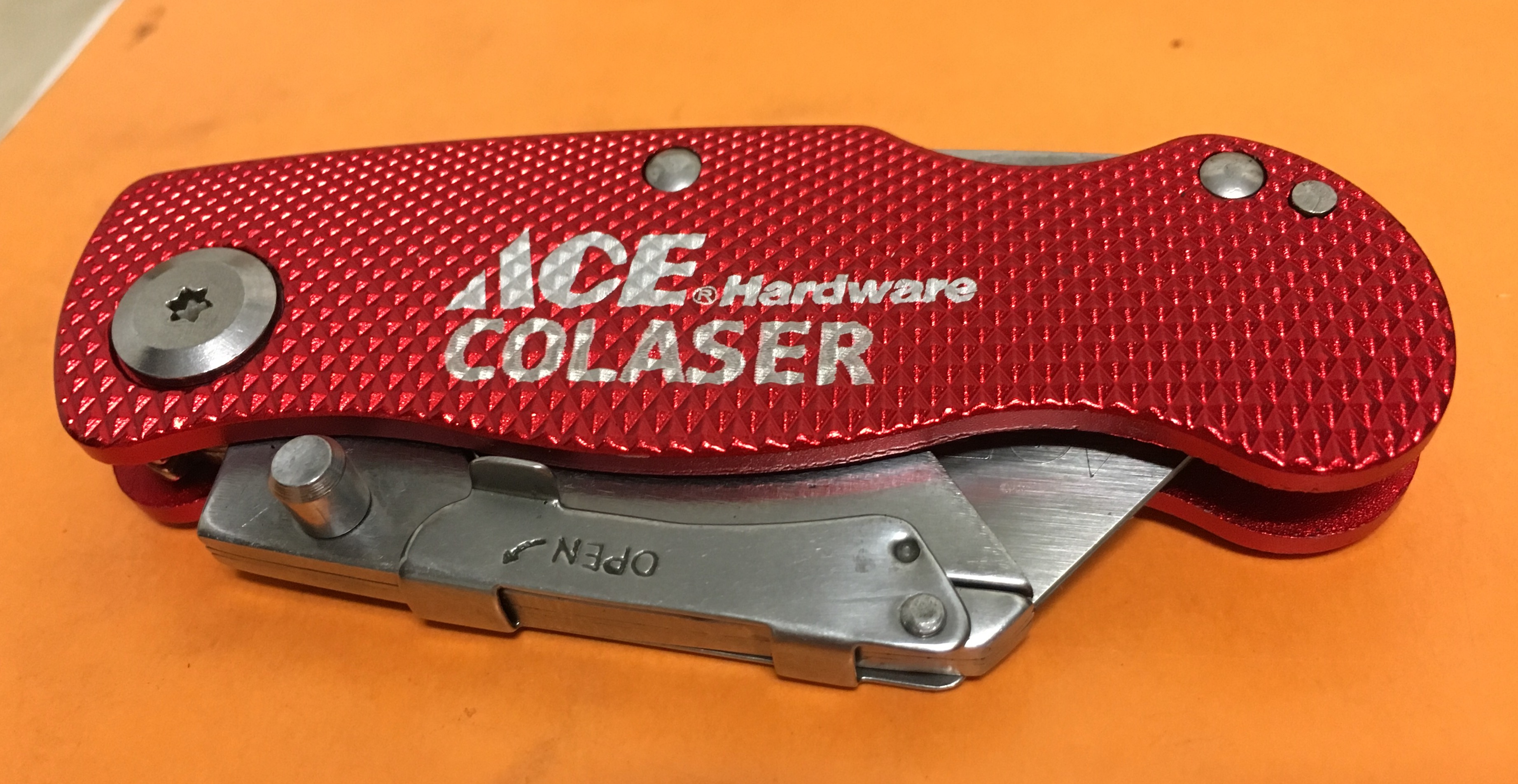
Engraving a Mirror
I’ve been wanting to try engraving a glass mirror. I picked up several 2-inch round mirrors from the craft store for a test.
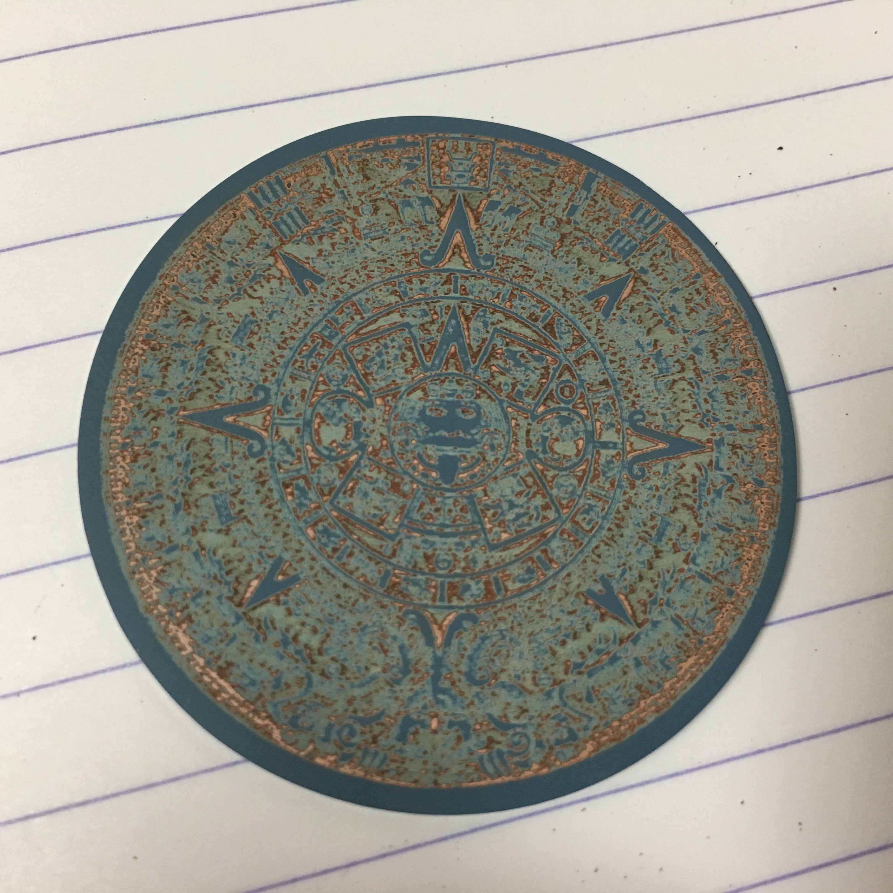
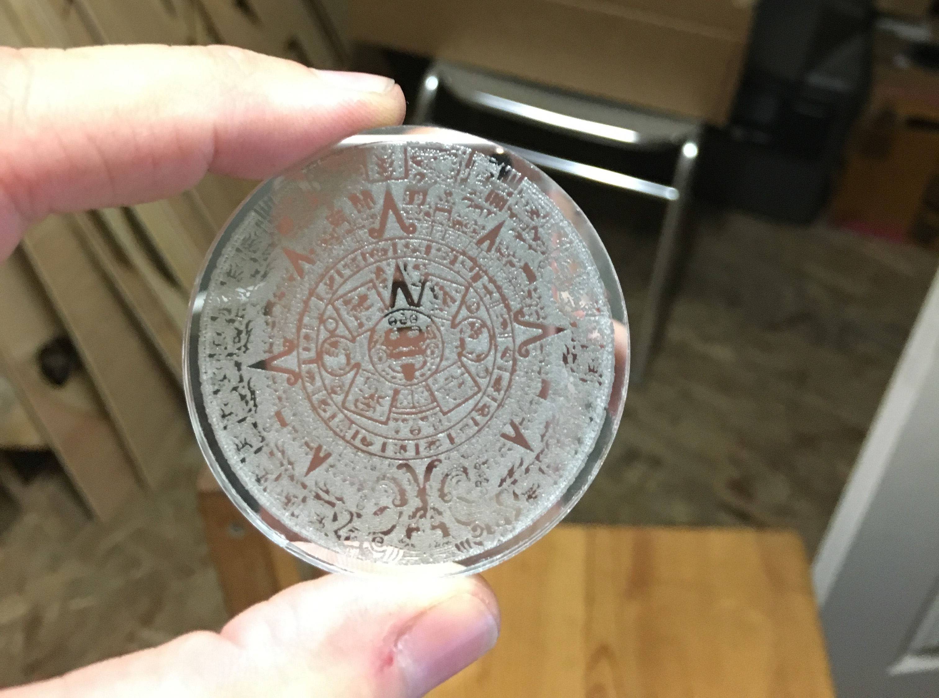
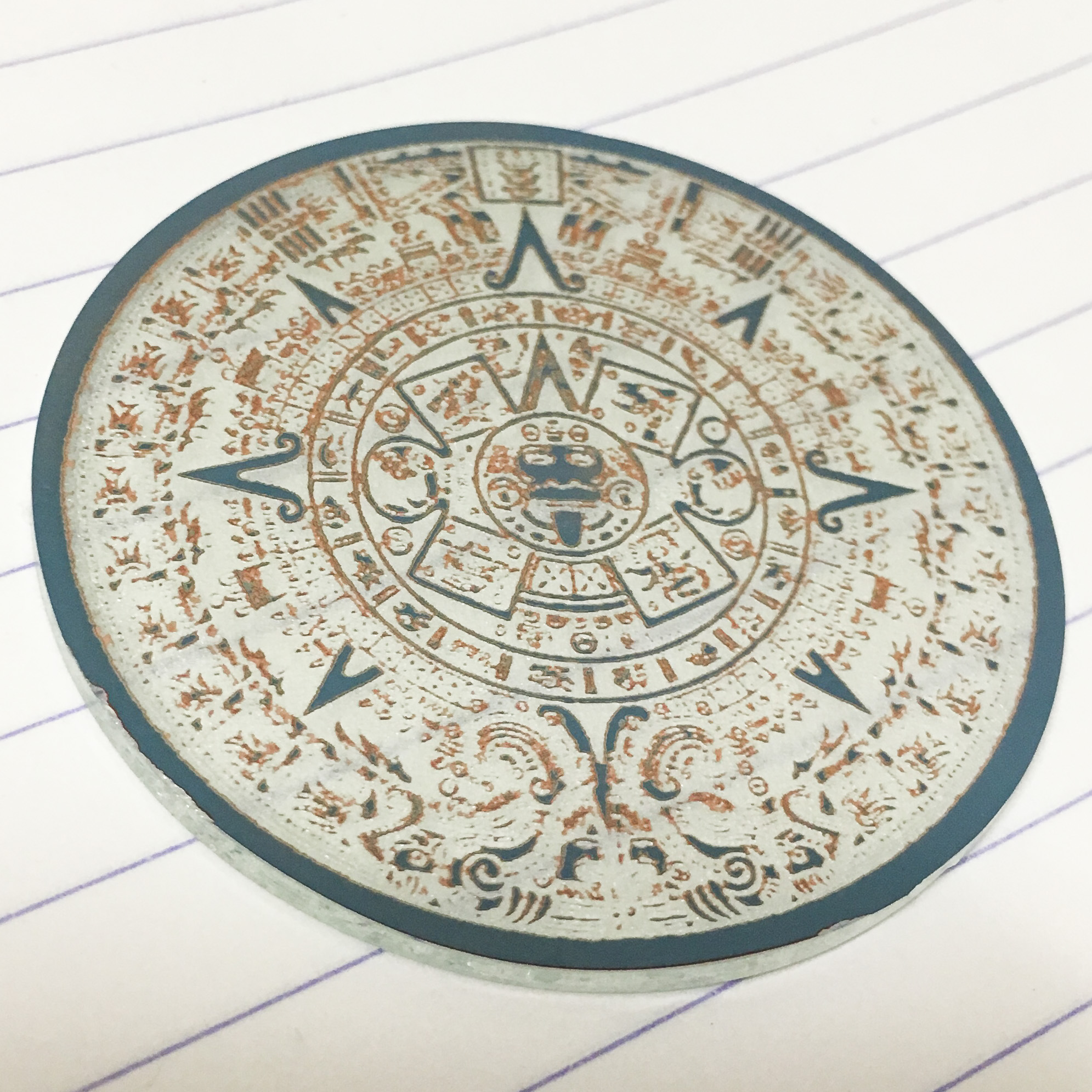
You could engrave from the front, which would be the same as engraving any kind of glass. You’d get a frosted effect. But what I wanted to try was engraving the back, through the metallized coating that turns a sheet of glass into a mirror.
For my first attempt I guessed 10 power and 100 speed, and that turns out not to be enough. It cut through the protective coating, and into the metal layer, but not through the metal. Interestingly, the metal layer appears to be copper colored from the back. I’m guessing that the white metal (do they still use silver?) reflective layer is very, very thin and copper is plated on top of it for protection.
Increasing the power to 30 created the effect I was looking for. It was immediately obvious that it was cutting through the metal, because the laser lit up the entire piece!
In the video you can see that I used some masking tape folded over to attach the mirror to a piece of scrap wood. Without the tape, the compressed air blast from the laser head was enough to float the mirror out of alignment. I engraved a circle on the wood to help me place the mirror accurately.
The final result is a little hard to visualize from a photograph, but it looks really cool in person. Sparkly! In the photo you can see the reflection of my rose gold iPhone (camera) in the parts of the mirror that are still mirror. The engraved parts appear frosted white.
Here’s what it looks like from the back:
The dark blue is the protective coating, which you can see has been removed in many places where the metal is left intact. It would probably be a good idea to re-coat the engraved mirror to keep the metal from corroding. Also, the edges are sharp, so some kind of mounting for it (or grinding the edges smooth) would be a good idea.
Trying to Match Epilog
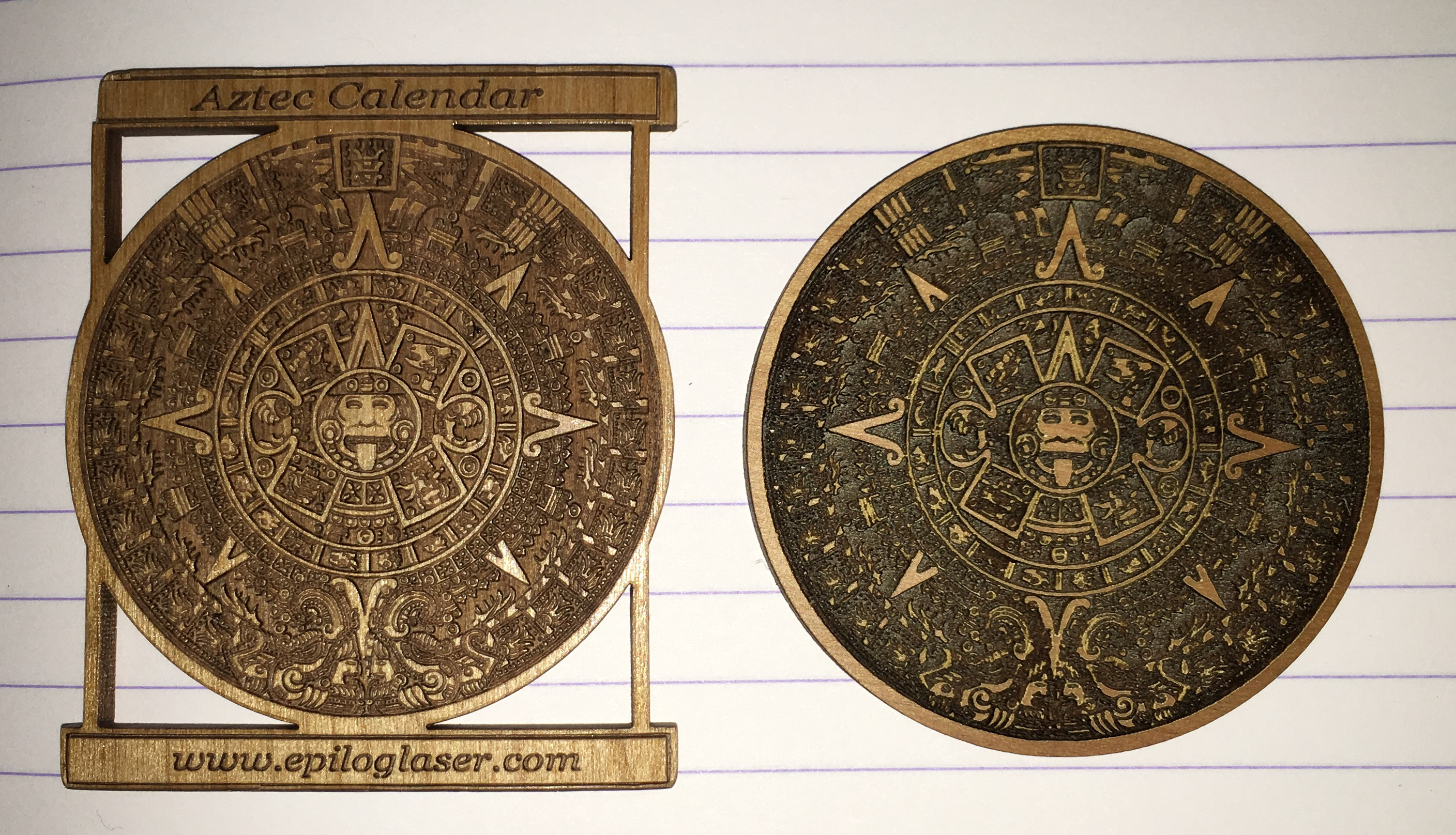
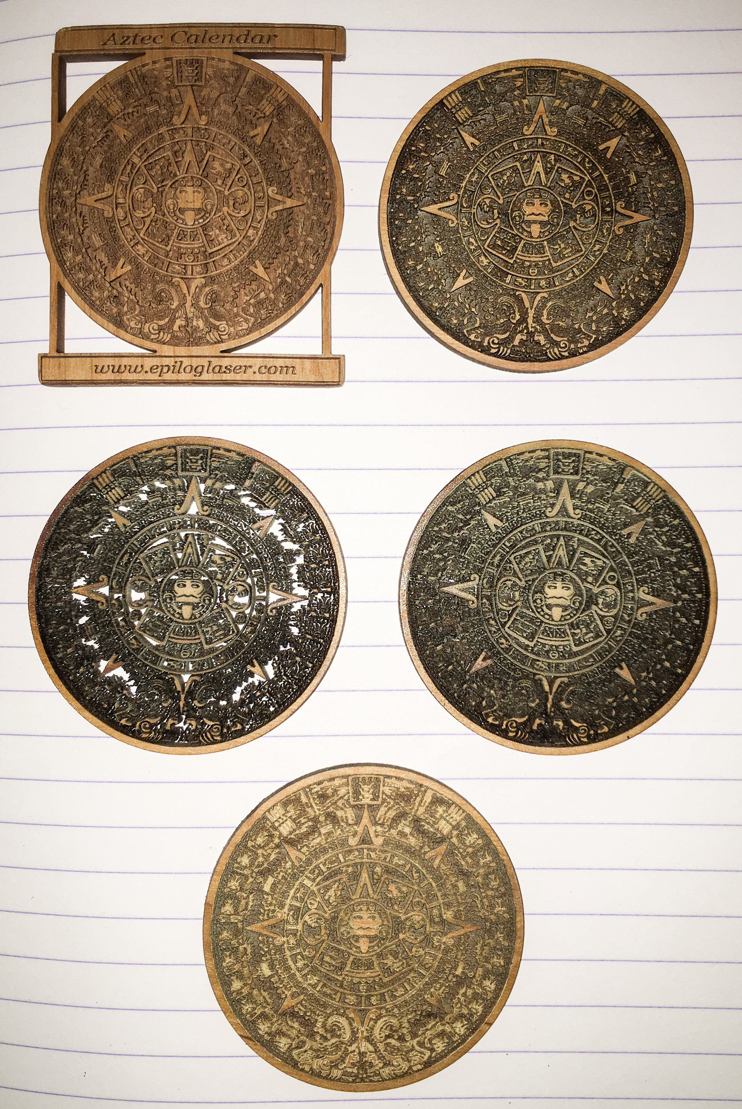
There were many fascinating things shown at San Diego MakerFaire recently. One of them was an Epilog laser cutter. Epilog is a U.S. brand that commands a significantly higher price than the Full Spectrum Laser we have, which is based on an imported Chinese product. Epilog lasers are known for doing very fine engraving. At MakerFaire, they were cutting and engraving a demonstration file, and handing them out, so I grabbed one. It was a detailed raster-engraved Aztec calendar about 2.1 inches in diameter, on 1/8-inch prefinished alder wood from LaserBits. I ordered the same wood (I think), found the same file online (minus the text), and tried to reproduce it on the Colaser.
Once I got the settings close, my results were actually pretty close to the Epilog sample.
I’m not sure why the engraved parts are darker on my version than on Epilog’s. Mine also needed wiping off after engraving, whereas the Epilog sample came out of the machine pretty clean. Comparing the detail closely, you can see that the Epilog held the finest detail a little better. It’s possible I could do better by more fiddling with settings. Maybe reducing both power and speed would work better.
This kind of detail is only possible with high quality wood. This 1/8″ alder is about $10 a square foot, if you order it in 6×12-inch sheets from LaserBits. It’s much nicer to work with than any of the plywoods I’ve tried.
Here are all my attempts.
The bottom one was under powered, and the two in the middle row were done at too high a power setting: the laser engraved right through the wood. I found that the raster power setting was quite non-linear, which is why it took so many tries. The setting I liked the best was 33 power, 100 speed.
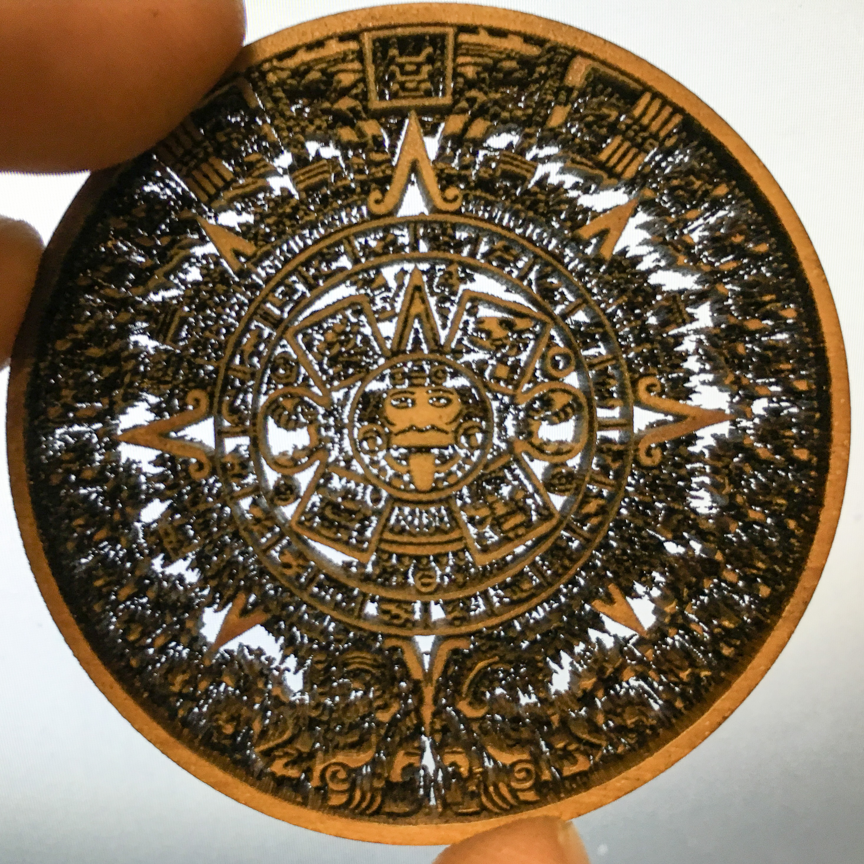
Engraving a highly detailed design all the way through makes a really cool filigree effect.
This design would be too fragile, but with some attention in the design to including a support structure, this would be sturdy enough for some purposes.

